
")
")
")
Modification of a regular LNB to a flanged one
The third position I went to was 36.0 ° E. From the point of view of the owner of a large dish, it is not very interesting. The signals of Russian providers for my position are not completely weak. At my reception, my colleague has a Gibertini 150 dish and receives Russian programs normally with a signal strength of over 10 dB. That's why I didn't expect any trouble. The volume directed towards Central Africa seemed too distant to me, so I didn't even think about it much.
Most receivable transponders use circular polarization. Its reception can be handled in two ways. The first option is to supplement the existing linear LNB with a polarizing plate in the waveguide. The theory of amateur production of such a plate is relatively widespread. A variety of replacement materials are recommended, from school plastic rulers to plastic credit cards. There are also countless different variants for dimensions and shapes. There are several theoretical mathematical procedures according to which it is possible to orient yourself a bit and work your way up to the optimal shape of the polarizing plate. Because I was interested in this topic before, I participated in attempts to receive the Tricolor on a 140 cm diameter dish with an amateur-made polarizing plate. The results were pathetic, so I rejected this path.
The second option is to buy an original LNB for circular polarization. But you need to think carefully about what you actually want to buy. Transmission at 36 ° E in circular polarization is located only above the frequency 11700 MHz. It is therefore possible to buy a single-band LNB designed only for this band. Narrowband promises better LNB parameters. But below this band are other programs with linear polarization that would not be possible to receive. So I opted for an LNB with a full Ku band. Here, too, it is necessary to think a little, because the two-band and universal variants are made. But beware, the universal ones are only for linear polarization, so you need to choose a two-band LNB. In addition, as it is not an LNB for regular European broadcasting, they have non-standard oscillator frequencies. This creates quite a lot of confusion for a beginner. I assumed that there would not be a lot of selection in our regular satellite e-shops, so I went to Ebay.
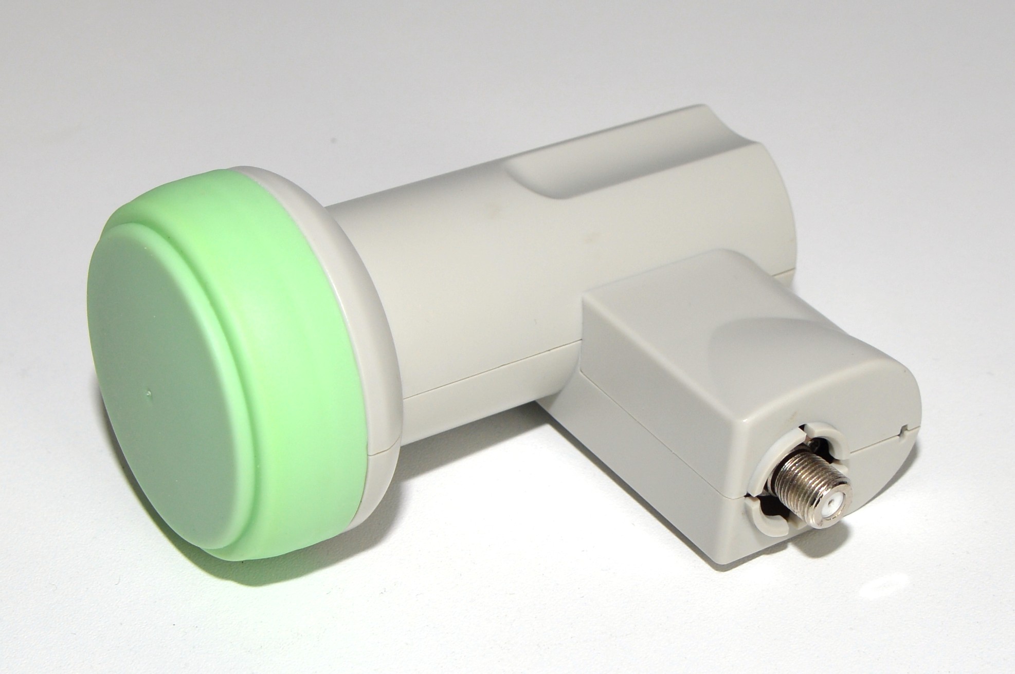
In the end, I bought the Galaxy Innovations GI-131. At first glance, it looks like a regular universal LNB. This is probably because even though I bought it in Russia, it is a German product. Unfortunately it's not flanged, so I couldn't use the feedhorn designed for my dish. But given the price of the LNB and the size of my plate, I didn't deal with it.
It soon became clear that this was a fundamental mistake. With this LNB and a 270 cm dish, I had a worse signal than the Gibertini 150 dish with the GI-121 LNB. I searched for the cause in the receiver settings for a while, because I had no experience with circular polarization. But I didn't find anything fundamental. So I started to think that an unsuitable feedhorn inside the LNB was to blame.
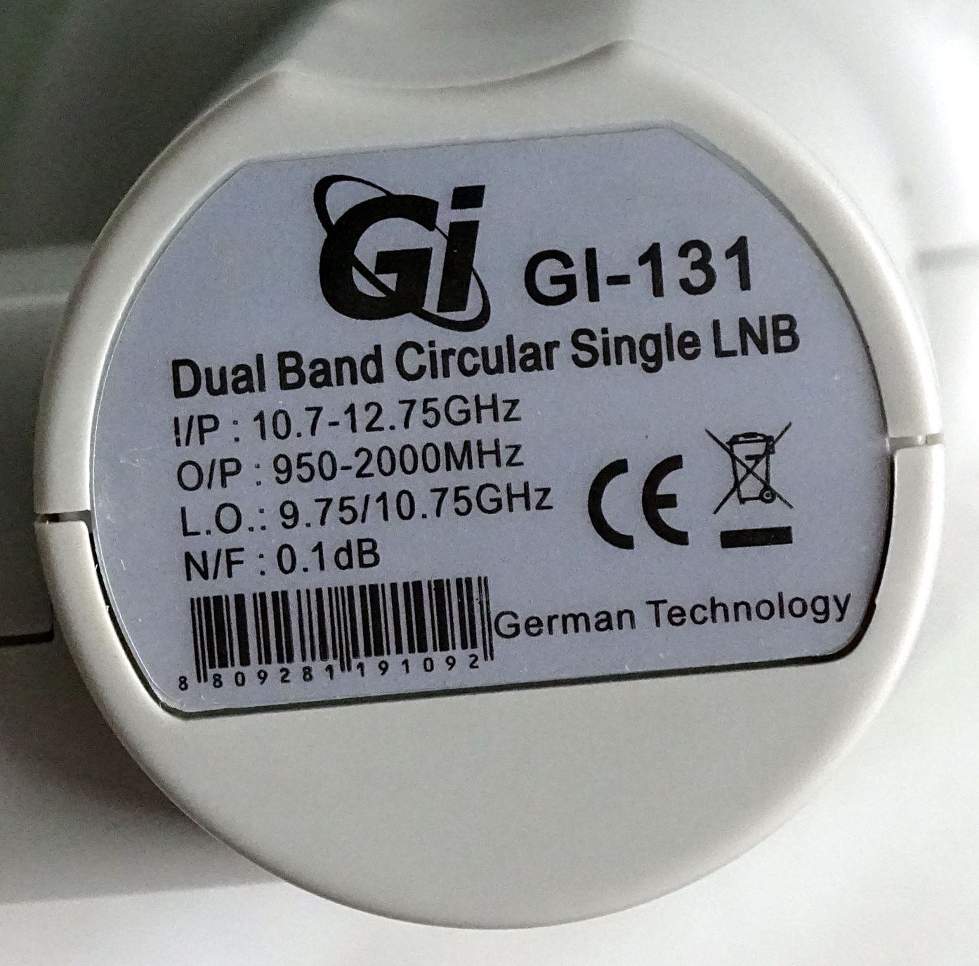
Because I had no idea if this type of LNB contained any more sophisticated feedhorn at all, I set about disassembling it. Because the whole cover is plastic and I didn't want to destroy it, it was necessary to use a simple trick. Cover plastics are sensitive to heat. When heated, they soften and can be shaped without cracking. I started with a green cap. I brought water to a boil in the pot and dipped the end of the LNB with the lid in for two minutes. Then it was possible to insert a screwdriver under the lid and carefully remove them. A metal feedhorn and a rubber sealing ring appeared under the lid. The rest of the cover was already snapped behind the classic packs, so it didn't even need to be heated. Using a knife, it was possible to tilt the packs and remove the cover.
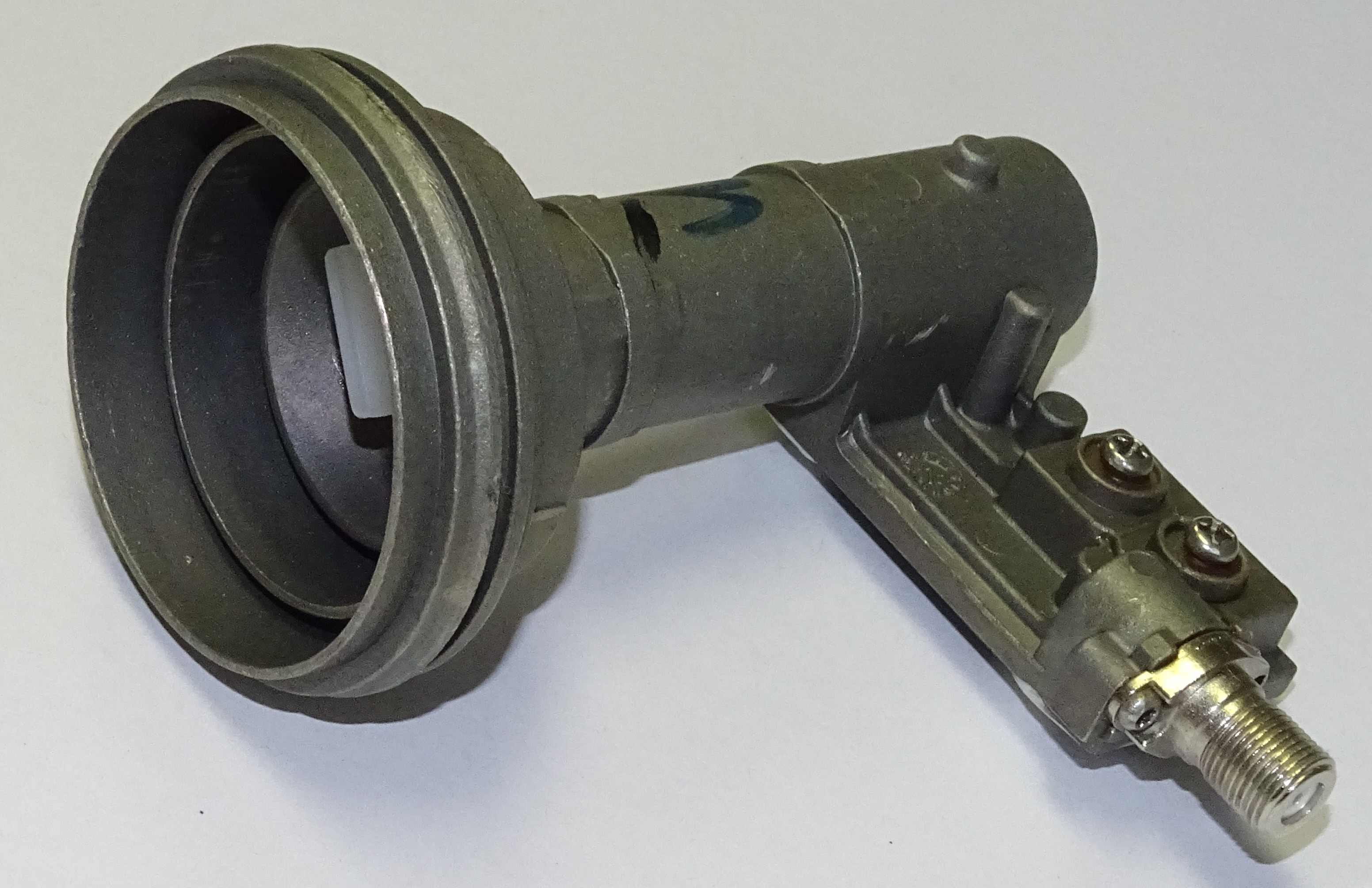
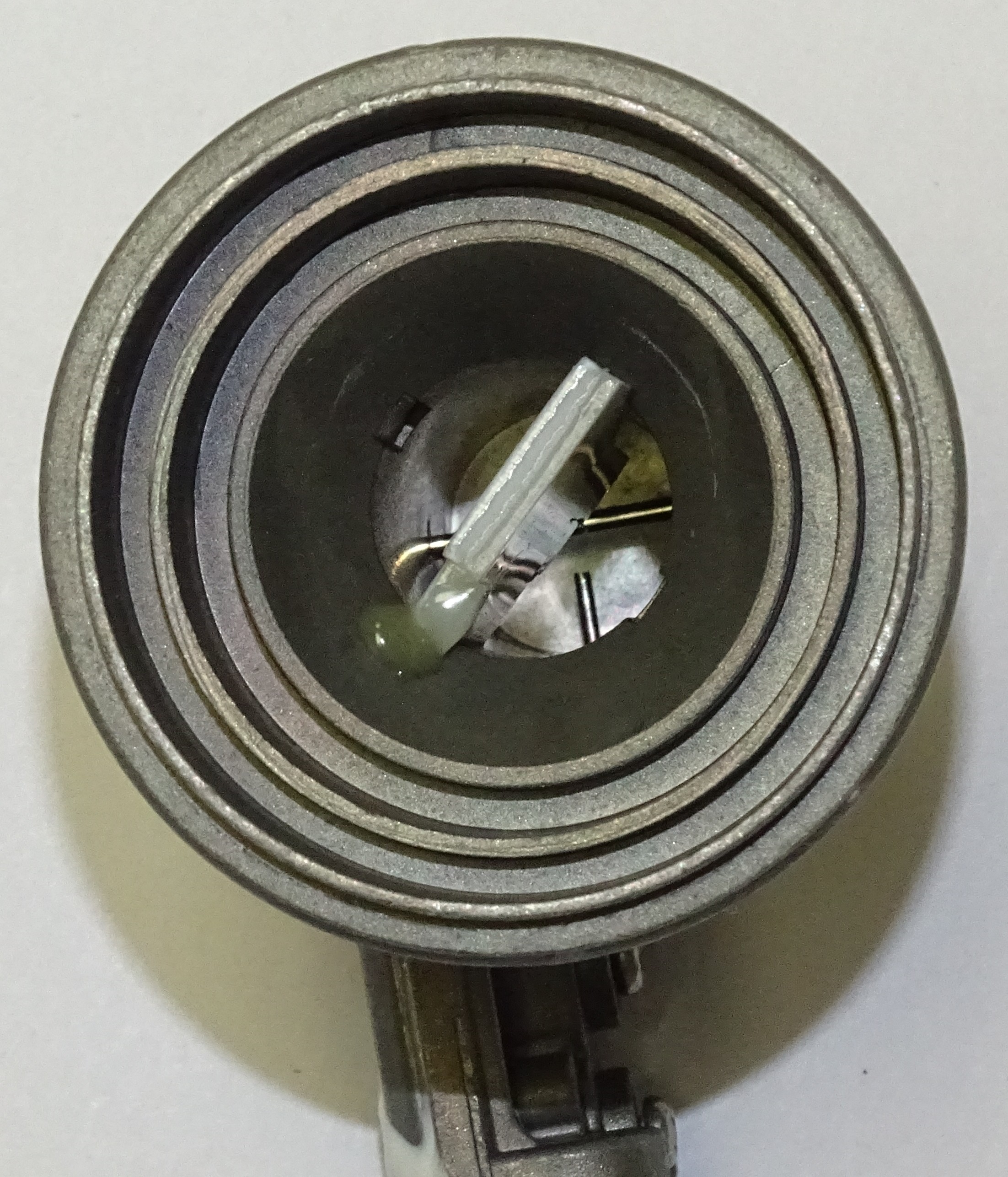
Fig. 5 - View of the original feedhorn
The exposed LNB shows that the feedhorn is actually under the plastic cover. Unfortunately, I can't figure out the parameters of the dimensions yet. I was quite surprised that the LNB contains a depolarization plate. I was expecting more of an original circular polarization antenna. This LNB proves that when it can, the depolarization plate works as it should. I compared the feedhorn with my original PO-40 and the differences in physical dimensions are fundamental. So I started thinking about how to adapt the LNB to a flanged version.
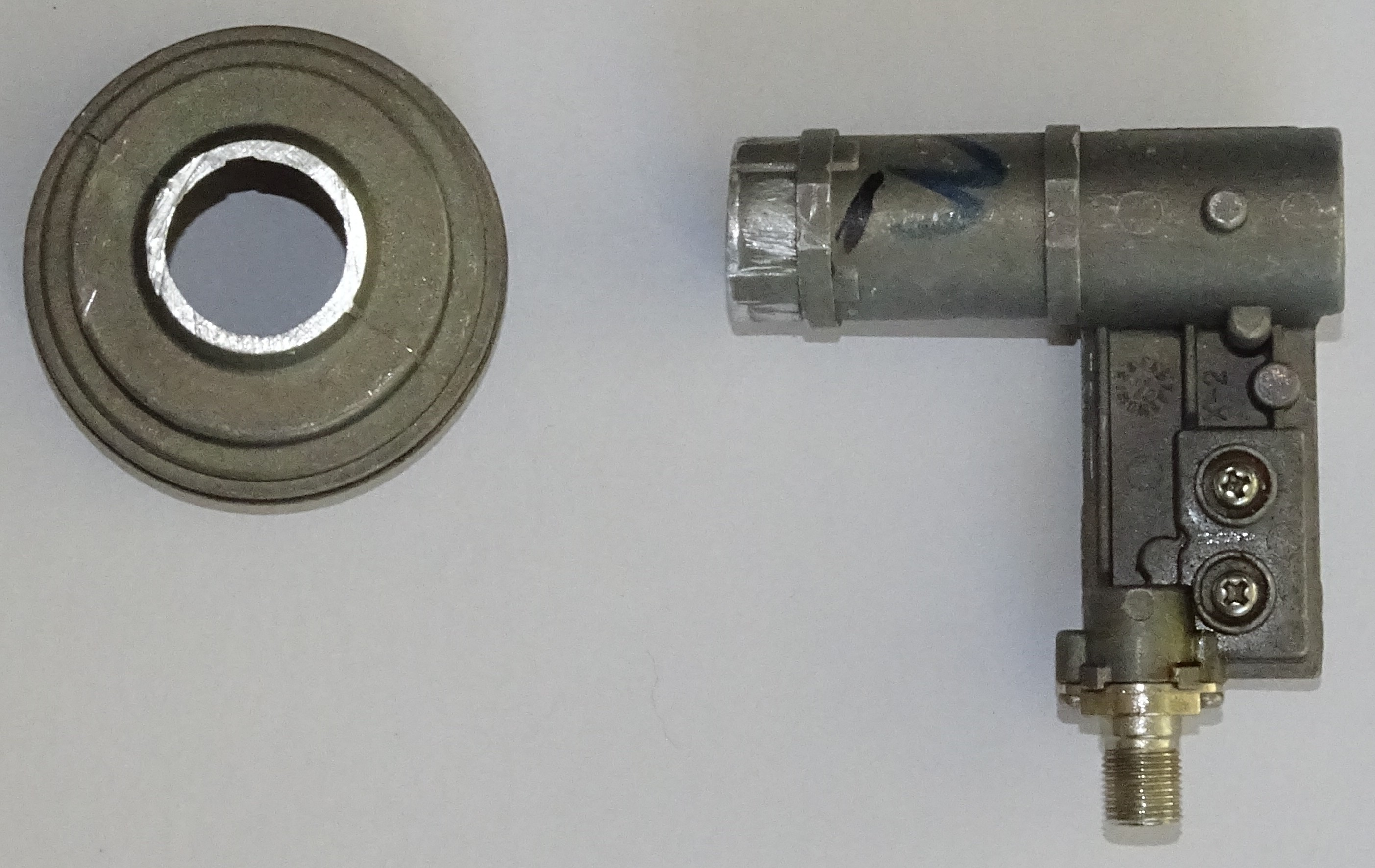
Fig. 6 - Cut off the original feedhorn
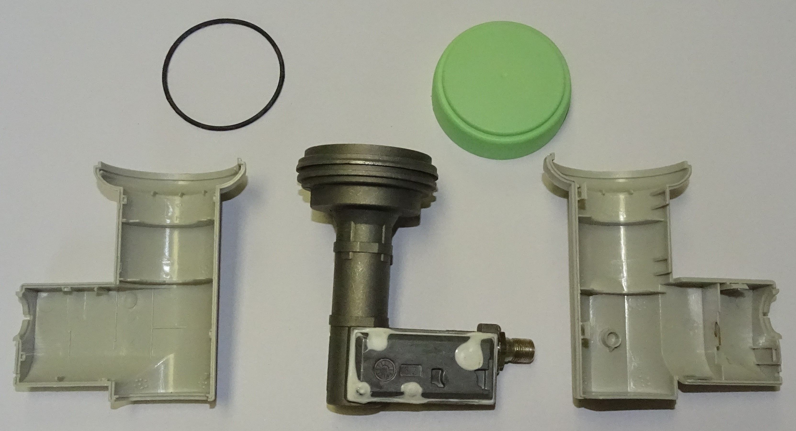
After a moment's thought, all considerations of the original LNB design went aside, and I set out to experiment. As a first step, I decided to separate the original feedhorn from the waveguide. This should be done correctly on the lathe so that the cutting plane is perpendicular to the waveguide axis. But I didn't have it available. So I clamped the waveguide in a large vice so that the edge of the feedhorn was as parallel as possible to the jaws of the vise. And then I cut off the feedhorn nicely on the jaws of the vice.
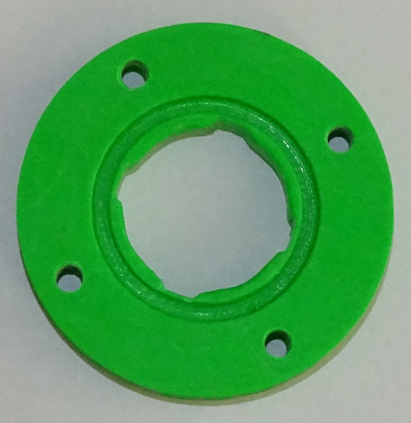
Fig. 7 - Plastic fastening intermediate ring
As a second step, I had the mounting ring printed on the 3D printer from ABS material. It turned out that the 3D printing was not accurate enough, so I had to fix the center hole a little by hand with a file. I cut an M4 thread into the four holes and checked that the LNB rubber sealing ring fitted into the groove. Originally, I wanted to attach the intermediate ring to the waveguide with instant glue. But because I enlarged the center hole by sawing, I managed to hit such a dimension that I hit the waveguide so tightly that it holds even without glue.
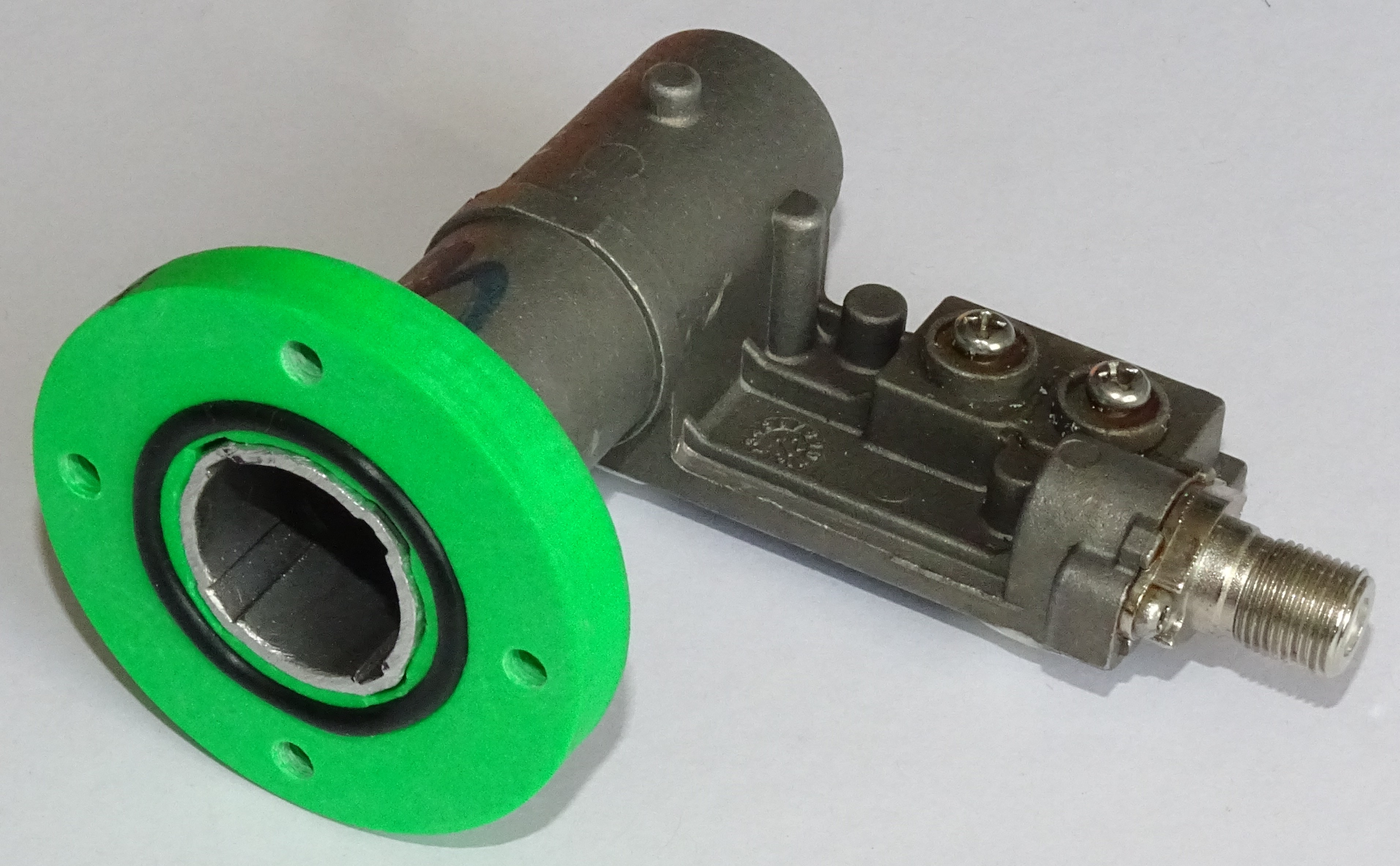
Fig. 8 - Intermediate ring mounted on the LNB waveguide
The intermediate ring is only 8 mm thick. I was a little worried that the interface between the ring perpendicular to the axis of the waveguide would be set. Thanks to the tight pressing of the plastic on the waveguide, the edge of the intermediate ring was placed exactly on the section of the waveguide, so that the deviation did not change much. It was then shown that the depolarization plate would extend about 20 mm into the waveguide of the newly attached feedhorn. It needed to be narrowed by 2 mm in the overhang to fit into the new 18 mm waveguide.
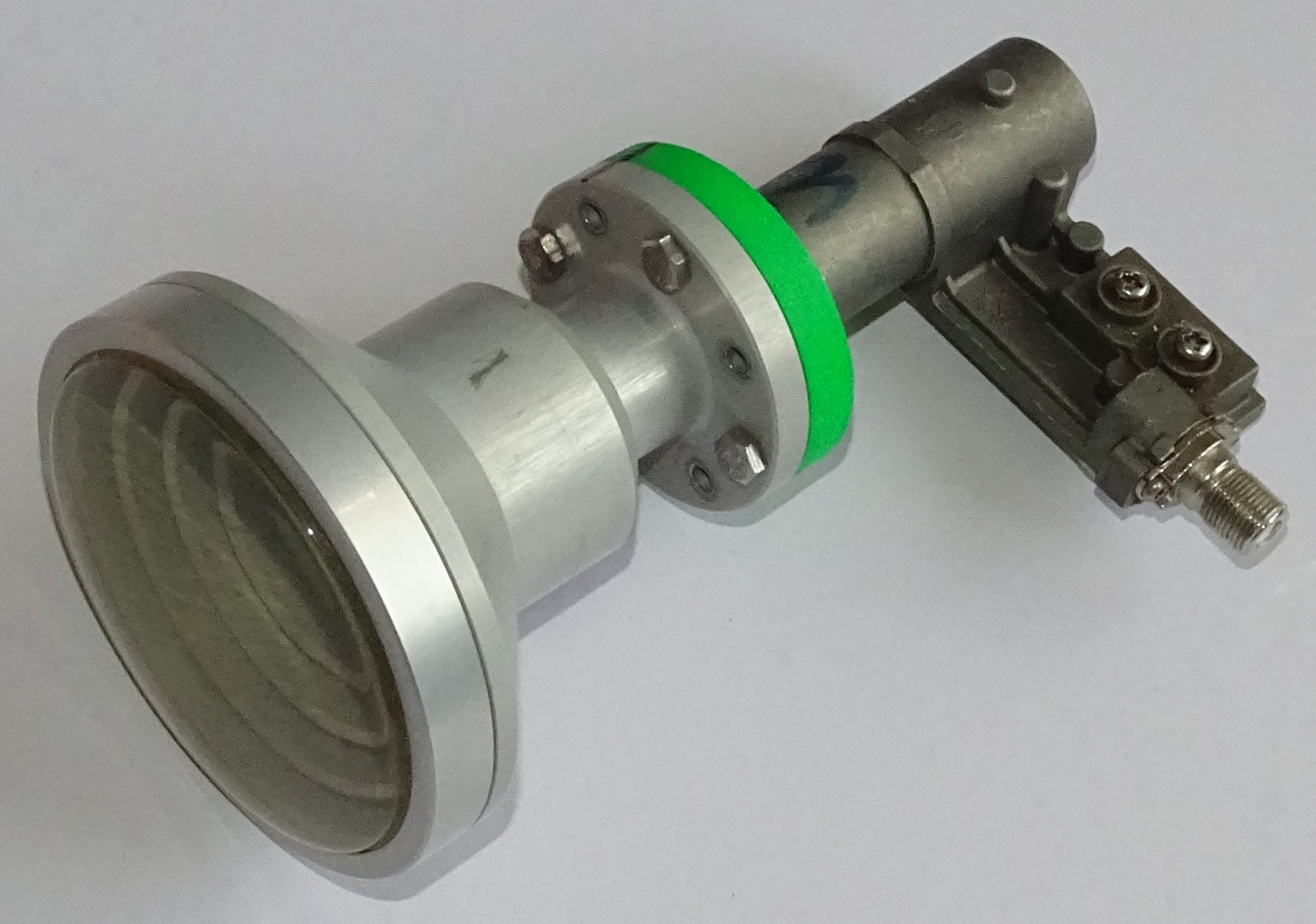
Fig. 9 - View of the LNB assembly with PO-40 feedhorn
Then I screwed the already modified LNB to the feed horn PO-40. I liked the overall set. But I was not very convinced of its functionality. What worried me most was whether the original waveguide was pressed precisely enough against the PO-40 waveguide. I suspected that any cracks could cause mischief. That's why I hurriedly tested this invention for live operation.
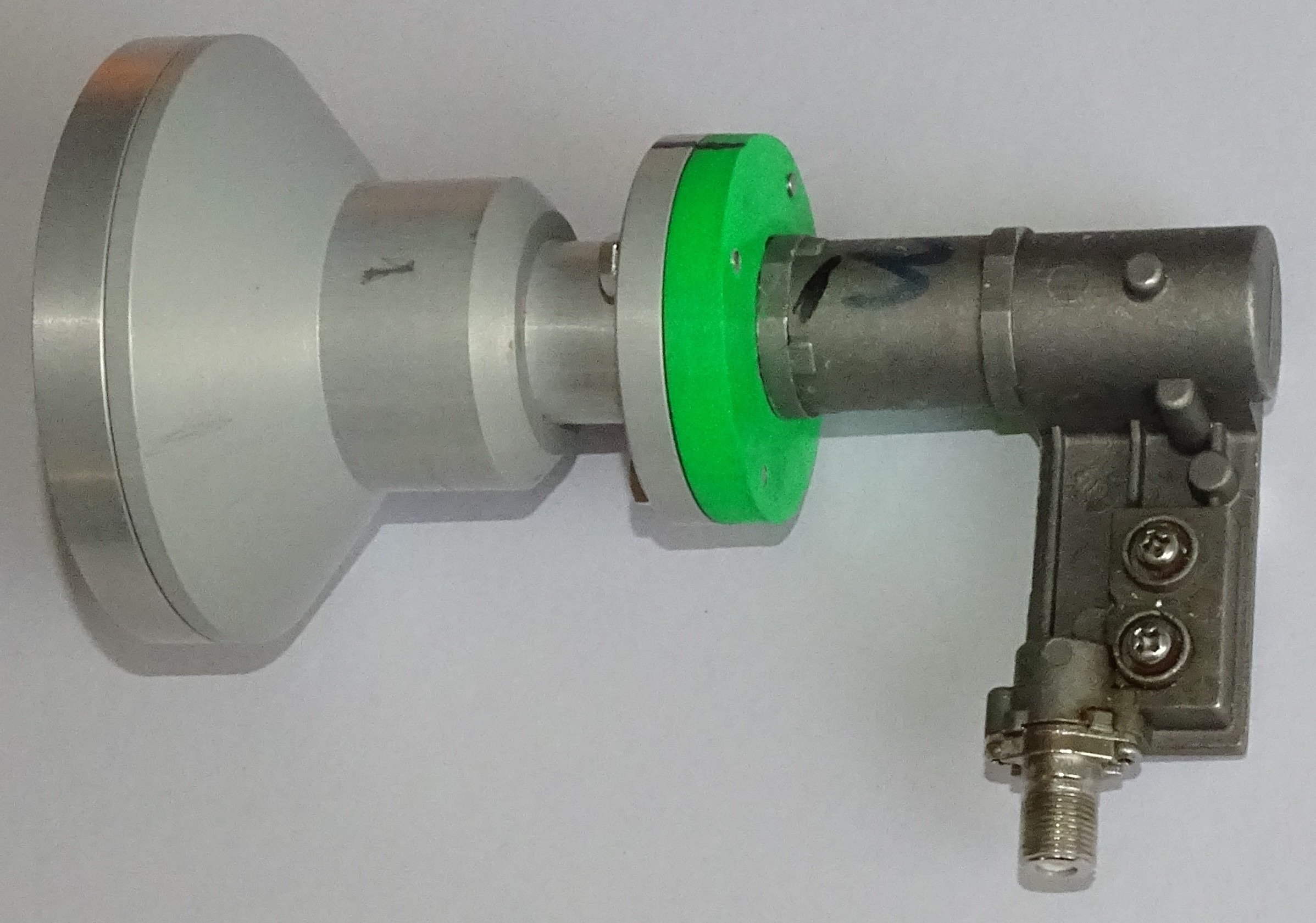
Fig. 10 - Another View of the LNB assembly
For comparison, I obtained data from the assembly Gibertiny150 x GI-121 and Laminas 2700 x GM-101 without modifications. To this I added data from the combination Laminas 2700 x modified GI-131. Of course, Gibertina is almost at the same location as my Laminas. The distance between the dishes is approximately 540 m as the crow flies. The good news is that the newly formed set works. This means that the signal from the PO-40 feedhorn reaches the LNB antenna and it is able to process this signal. The bad news is that only left-handed polarization works this way. Clockwise polarization has a signal strength of about 5 percent and is completely unusable. It could be assumed that I damaged the LNB by my reckless treatment. But the truth is that there have been problems with this polarization before - it only jumped occasionally. At the time, I attributed it to an inappropriate feedhorn. But who knows ... And now an overview table with measured values.
|
Transpondér |
Offset parabola Gibertini 1500 |
Offset parabola Laminas 2700 |
|
| LNB GI-121 [%] |
LNB GM-101 original [%] |
LNB GI-131 + PO-40 [%] |
|
| 16/2/2022 cloudy |
12/2/2022 | 16/2/2022 light rain |
|
| 11727 / L / 8PSK | 75 | 69 | 91 |
| 11747 / R / 8PSK | 93 | 65 | 0 ÷ 5 |
| 11766 / L / 8PSK | 75 | 60 | 90 |
| 11785 / R / 8PSK | 79 | 52 | 0 ÷ 5 |
| 11804 / L / 8PSK | 78 | 66 | 96 |
| 11823 / R / 8PSK | 77 | 53 | 0 ÷ 5 |
| 11843 / L / 8PSK | 75 | 65 | 91 |
| 11862 / R / 8PSK | 76 | 54 | 0 ÷ 5 |
| 11881 / L / 8PSK | 78 | 68 | 87 |
| 11900 / R / 8PSK | 77 | 56 | 0 ÷ 5 |
| 11919 / L / 8PSK | 79 | 68 | 82 |
| 11938 / R / 8PSK | 76 | 56 | 0 ÷ 5 |
| 11958 / L / 8PSK | 78 | 69 | 77 |
| 11977 / R / 8PSK | 76 | 57 | 0 ÷ 5 |
| 11996 / L / 8PSK | 78 | 72 | 74 |
| 12015 / R / 8PSK | 74 | 61 | 0 ÷ 5 |
| 12034 / L / 8PSK | 80 | 74 | 72 |
| 12054 / R / 8PSK | 70 | 0 | 0 ÷ 5 |
| 12073 / L / 8PSK | 85 | 85 | 88 |
| 12111 / L / 8PSK | 81 | 93 | 96 |
| 12149 / L / 8PSK | 72 | 87 | 87 |
| 12174 / L / QPSK | 70 | 76 | 84 |
| 12190 / L / 8PSK | 74 | 89 | 92 |
| 12226 / L / QPSK | 87 | 99 | 99 |
| 12265 / L / QPSK | 81 | 90 | 86 |
| 12284 / R / 8PS | 75 | 77 | 0 ÷ 5 |
| 12303 / L / 8PSK | 74 | 80 | 73 |
| 12322 / R / 8PSK | 76 | 77 | 0 ÷ 5 |
| 12341 / L / QPSK | 82 | 84 | 76 |
| 12360 / R / 8PSK | 79 | 79 | 0 ÷ 5 |
| 12380 / L / 8PSK | 75 | 82 | 73 |
| 12399 / R / 8PSK | 75 | 72 | 0 ÷ 5 |
| 12418 / L / 8PSK | 77 | 79 | 71 |
| 12437 / R / 8PSK | 78 | 72 | 0 ÷ 5 |
| 12456 / L / 8PSK | 75 | 78 | 74 |
| 12476 / R / 8PSK | 75 | 72 | 0 ÷ 5 |
These data show that the result is more than contradictory. At lower frequencies the signal is stronger than from the unmodified LNB GM-101, but at higher frequencies it is the same or even worse. In any case, comparable results can be obtained with the Gibertina150 dish. And that's definitely wrong. I expected the signal strength of all transponders to the maximum. The question is whether to look for the cause of the failure only in the adjustment made, or whether another problem has arisen. It is worth noting the frequency 12054 / R / 8PSK, where I had a signal strength of 0 even with an unmodified LNB, which is quite strange. Any parasitic resonance, standing waves? It will probably be necessary to think carefully about the situation. And be sure to consult someone more experienced. :-)