
")
")
")
First experiments with the use of a polarizing plate
This article follows the description: modification of a regular LNB to a flanged one. The purchase and subsequent results with the LNB type GI-131 and GM-101 for circular polarization greatly disappointed my original expectations. Even attempts to connect the correct feedhorn PO-40 to LNB GI-131 did not lead to the expected increase in the strength of the received signal. That's why I decided to do another experiment.
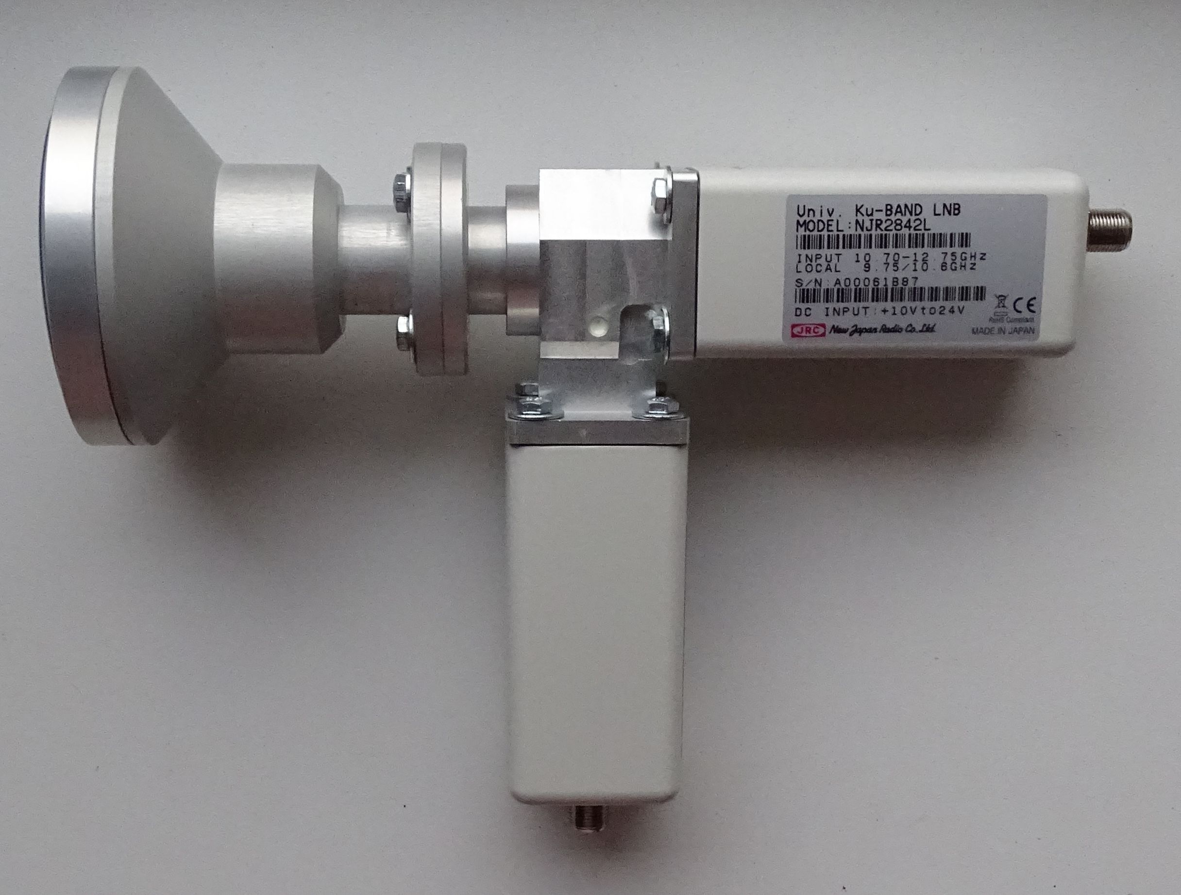
Fig. 1 - Assembly of components: Feedhorn - Ortho Mode Transducer - 2x LNB
For linear polarization, I use a pair of single-polarity LNB NJR2842 with a C120/WR75 polarization switch and an original PO-40 feedhorn. So I decided to use the polarizing plate from LNB GI-131 and put it in the waveguide of my system for linear polarization. This experiment is supported by the fact that the plate is made of the right material and at the same time has a shape that is functional. These are the two basic parameters on which experiments with an amateur-made polarizing plate could fail. Basically, it was just a matter of correctly placing the finished plate in another waveguide.
The original LNB has notches in its metal body to precisely position the polarizing plate, so the plate is slightly wider than the diameter of the waveguide. To use it in the new system, I had to narrow it down to 18 mm. The size was adjusted so that the plate could be tightly pressed into the waveguide and there was no need to fix it in the selected position. The only question was how deep to place the plate in the waveguide. In the original LNB, the plate started at the mouth of the feedhorn and led to a distance of 17 mm from the first antenna in the LNB.
Something like this could not be observed in my attempt, because the sum of the lengths of the waveguides of the feedhorn and the polarization switch was significantly larger. That's why I tested two positions of the plate. In position No. 1, the indicated plate was 17 mm from the point where the polarization switch divides the signal into two separate waveguides. In position 2, the plate was placed on the edge of the PO-40 feedhorn as it touched the feedhorn of the original LNB.
The results compared to LNB GI-121 are in the following table.
| Satellite |
Transponder |
Offset parabola Laminas 2700 |
||
| LNB GI-121 [%] |
LNB |
LNB 2x NJR2842 + plate Position 2 [%] |
||
| 5/3/2022 16:15 |
5/3/2022 17:15 |
5/3/2022 18:00 |
||
| Eutelsat 36B | 11727 / L / 8PSK | 95 | 82 | 83 |
| AMU1 | 11747 / R / 8PSK | 99 | 56 | 60 |
| Eutelsat 36B | 11766 / L / 8PSK | 93 | 74 | 75 |
| Eutelsat 36B | 11785 / R / 8PSK | 99 | 55 | 66 |
| Eutelsat 36B | 11804 / L / 8PSK | 99 | 75 | 75 |
| Eutelsat 36B | 11823 / R / 8PSK | 99 | 56 | 67 |
| Eutelsat 36B | 11843 / L / 8PSK | 97 | 73 | 74 |
| Eutelsat 36B | 11862 / R / 8PSK | 99 | 50 | 73 |
| Eutelsat 36B | 11881 / L / 8PSK | 99 | 74 | 74 |
| Eutelsat 36B | 11900 / R / 8PSK | 99 | 50 | 75 |
| Eutelsat 36B | 11919 / L / 8PSK | 99 | 67 | 75 |
| Eutelsat 36B | 11938 / R / 8PSK | 95 | 49 | 75 |
| Eutelsat 36B | 11958 / L / 8PSK | 96 | 70 | 76 |
| Eutelsat 36B | 11977 / R / 8PSK | 96 | 46 | 74 |
| Eutelsat 36B | 11996 / L / 8PSK | 98 | 66 | 77 |
| Eutelsat 36B | 12015 / R / 8PSK | 94 | 44 | 75 |
| Eutelsat 36B | 12034 / L / 8PSK | 99 | 61 | 79 |
| Eutelsat 36B | 12054 / R / 8PSK | 0 (83) | 0 (40) | 0 (68) |
| AMU1 | 12073 / L / 8PSK | 99 | 57 | 75 |
| AMU1 | 12111 / L / 8PSK | 99 | 46 | 80 |
| Eutelsat 36B | 12149 / L / 8PSK | 95 | 57 | 80 |
| AMU1 | 12174 / L / QPSK | 86 | 43 | 60 |
| AMU1 | 12190 / L / 8PSK | 96 | 46 | 73 |
| AMU1 | 12226 / L / QPSK | 99 | 67 | 81 |
| AMU1 | 12265 / L / QPSK | 99 | 64 | 72 |
| AMU1 | 12284 / R / 8PS | 89 | 41 | 54 |
| AMU1 | 12303 / L / 8PSK | 91 | 55 | 64 |
| AMU1 | 12322 / R / 8PSK | 90 | 41 | 54 |
| AMU1 | 12341 / L / QPSK | 94 | 55 | 61 |
| AMU1 | 12360 / R / 8PSK | 92 | 39 | 51 |
| AMU1 | 12380 / L / 8PSK | 95 | 47 | 58 |
| AMU1 | 12399 / R / 8PSK | 89 | 40 | 44 |
| AMU1 | 12418 / L / 8PSK | 93 | 42 | 63 |
| AMU1 | 12437 / R / 8PSK | 90 | 23 | 55 |
| AMU1 | 12456 / L / 8PSK | 95 | 58 | 57 |
| AMU1 | 12476 / R / 8PSK | 91 | 39 | 54 |
From the given data, it follows that the position of the polarizing plate in the throat of the feedhorn brings much better results. However, this combination does not reach the qualities of LNB GI-121. The signal was measured by the VU+Ultimo4k receiver with the "Satellite search" plugin. While the signal strength from LNB GI-121 was stable and varied by a maximum of one percent, the signal strength in the next two columns fluctuated within a few minutes up to ten percent and the AGC value also varied. The given numbers are therefore only a subjective average of the value that was displayed the longest. Noteworthy is the 12054 / R / 8PSK frequency on the red line. The "Satellite search" plugin here indicates a signal strength of 0. Despite this, programs in UHD resolution (for example Eurosport 1) with the strength indicated in brackets will be tuned to the specified frequency. It seems that the authors of the plugin had a bug somewhere. Both in the VTI firmware and in Openatv.
To be honest, I don't want to draw any conclusions from the measured values. It looks more like a long experiment. And I don't want to do that at all. By nature, I am more of a lazy technician who calculates something theoretically, then manufactures it according to these calculations and it works on the first try. I would really like that.
19.3.2022 supplement.
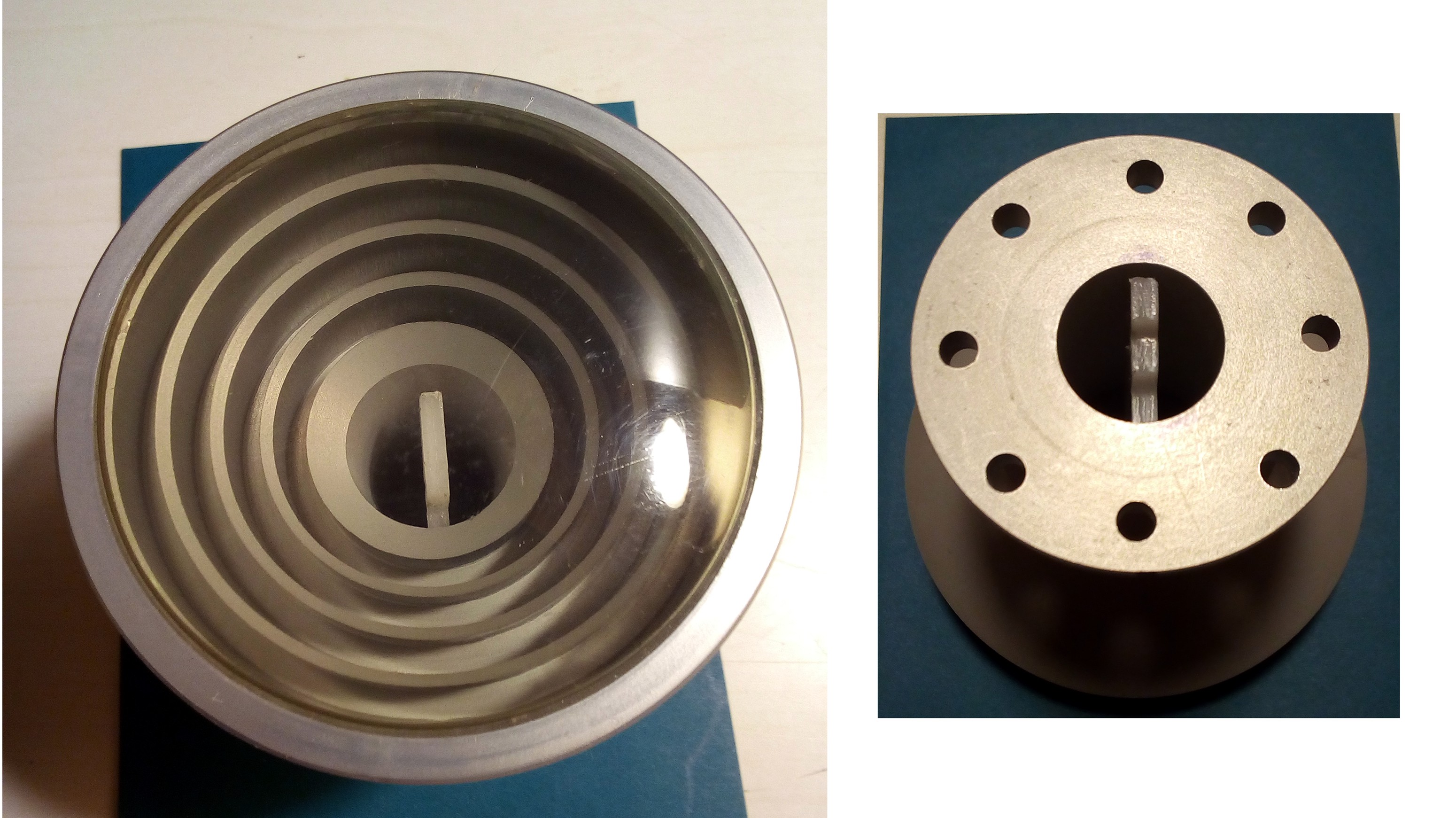
I devoted today to further experiments with circular polarization reception. I got my hands on a professional depolarizer XD12 from Swedish Microwave. I was hoping that this would solve the circular polarization reception for good. Unfortunately, I sobered up very quickly.
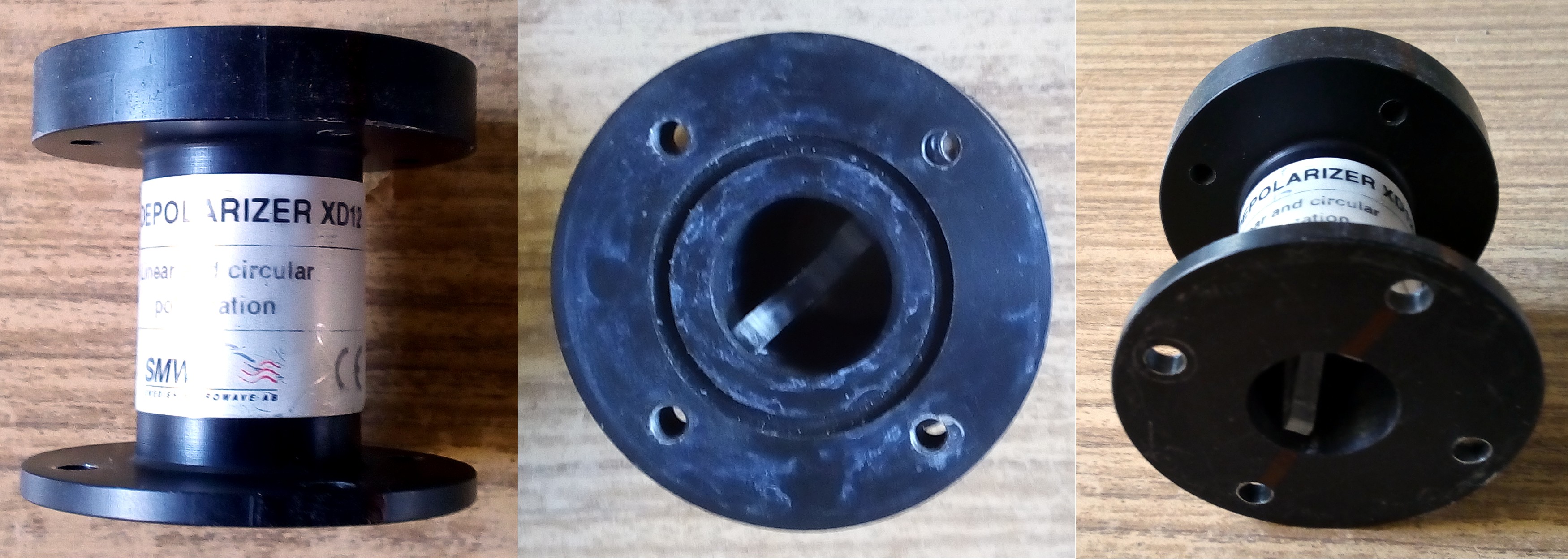
The first disappointment came when I wanted to screw the depolarizer to my polarization switch. Both components have only four mounting holes, so they can only be rotated 90° relative to each other. You probably already guessed that the depolarization plate was parallel or perpendicular to the polarization plane of the crossover. So the correct slope of 45° could not be set. For a while I couldn't understand why two professional components made to standards could not be connected properly. Then I began to determine how firmly the plate is held in the waveguide of the depolarizer. And to my surprise, after a slight push, it slid out.
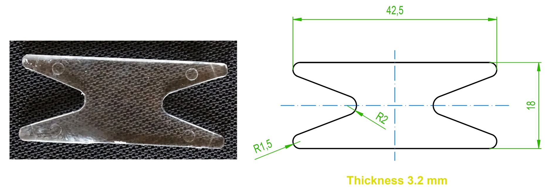
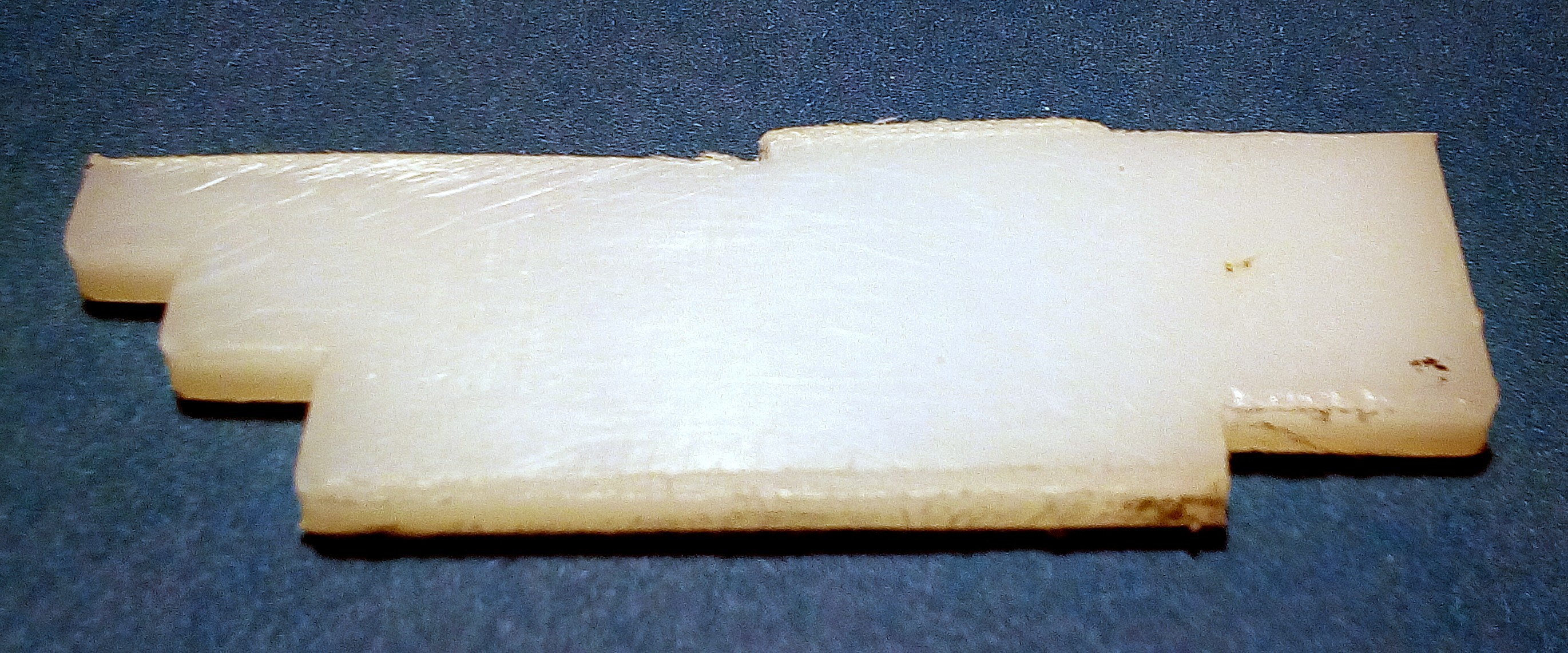
Fig. 6 - Polarization plate from XD12
In terms of material, it looks like ordinary Plexiglas. Unlike the previous plate from LNB GI-131, the shape is axisymmetric. This seemed important to me because the input to my polarization crossover is also symmetrical. After a moment's hesitation, I inserted the plate into the waveguide of my PO-40 feedhorn.
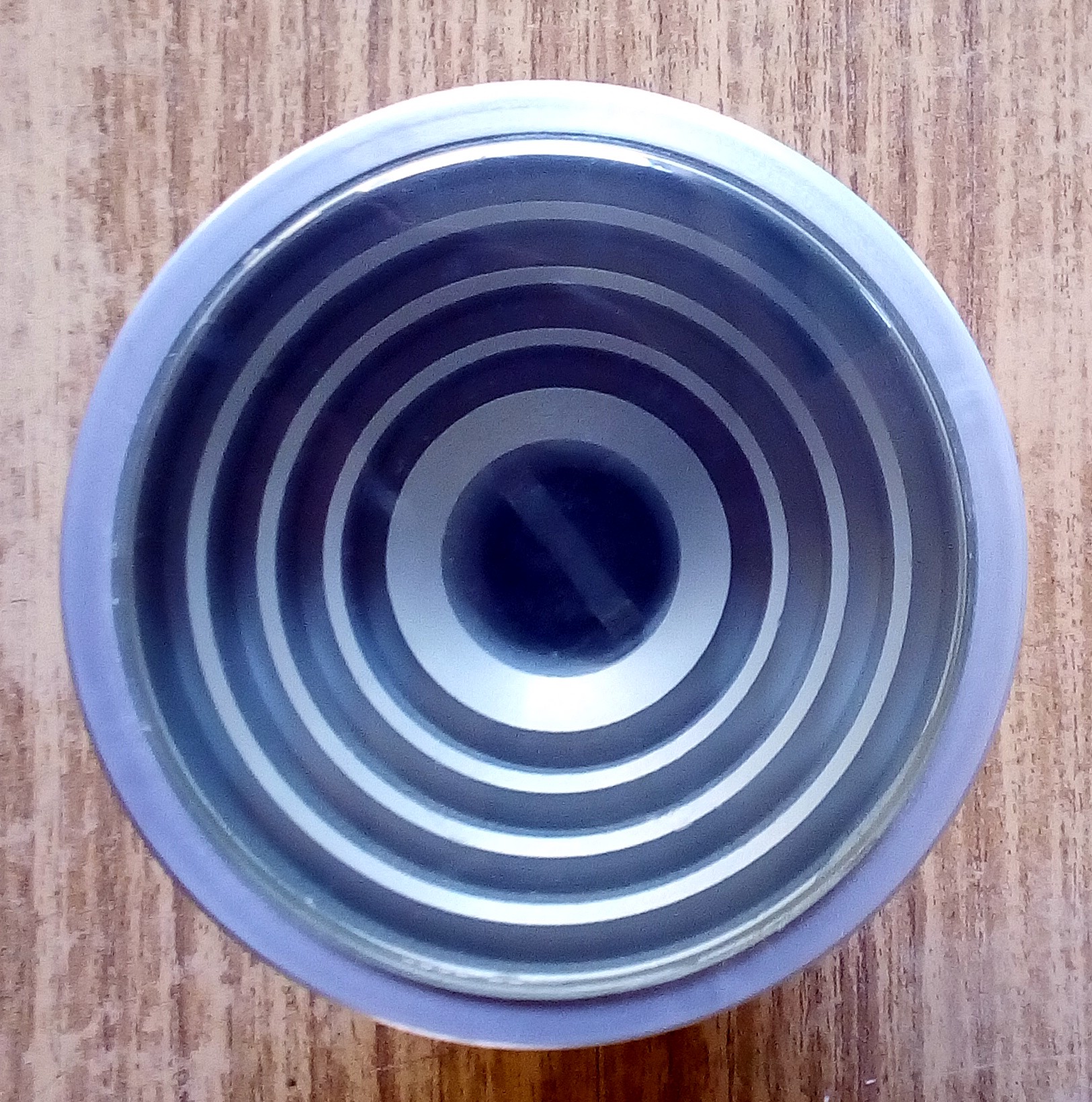
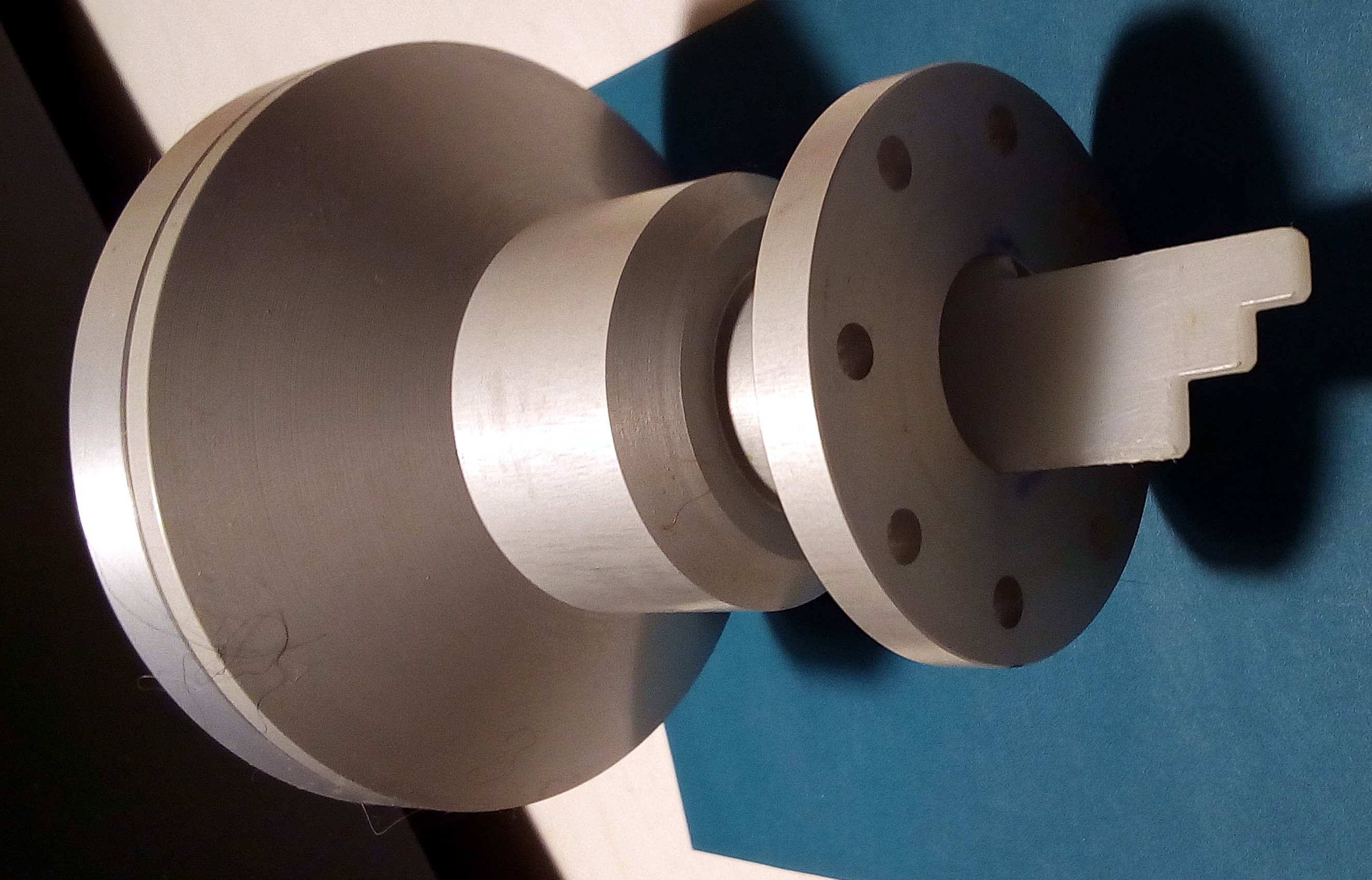
Fig. 7 - Plate from XD12 in feedhorn PO-40
I placed it on the inner edge of the waveguide, as in the tests of the previous board from LNB GI-131, when I measured better results in this position (Position 2). To compare the current signal strength, I also wrote down the values measured just before replacing the polarizing plate. And you can see the result in the following table.
| Satellite |
Transponder |
Offset parabola Laminas 2700 |
|||
|
Previous |
Plate |
Depolarizer SMW XD12 [%] |
LNB |
||
| 19/3/2022 15:15 |
19/3/2022 16:00 |
19/3/2022 16:45 |
19/3/2022 17:15 |
||
| Eutelsat 36B | 11727 / L / 8PSK | 88 | 88 | 88 | 88 |
| AMU1 | 11747 / R / 8PSK | 80 | 74 | 89 | 87 |
| Eutelsat 36B | 11766 / L / 8PSK | 73 | 82 | 83 | 83 |
| Eutelsat 36B | 11785 / R / 8PSK | 67 | 82 | 81 | 82 |
| Eutelsat 36B | 11804 / L / 8PSK | 79 | 85 | 88 | 92 |
| Eutelsat 36B | 11823 / R / 8PSK | 66 | 80 | 83 | 86 |
| Eutelsat 36B | 11843 / L / 8PSK | 78 | 91 | 85 | 93 |
| Eutelsat 36B | 11862 / R / 8PSK | 71 | 82 | 82 | 88 |
| Eutelsat 36B | 11881 / L / 8PSK | 85 | 90 | 82 | 90 |
| Eutelsat 36B | 11900 / R / 8PSK | 72 | 82 | 81 | 88 |
| Eutelsat 36B | 11919 / L / 8PSK | 84 | 88 | 84 | 91 |
| Eutelsat 36B | 11938 / R / 8PSK | 71 | 88 | 86 | 82 |
| Eutelsat 36B | 11958 / L / 8PSK | 78 | 80 | 82 | 86 |
| Eutelsat 36B | 11977 / R / 8PSK | 69 | 88 | 83 | 76 |
| Eutelsat 36B | 11996 / L / 8PSK | 78 | 80 | 85 | 82 |
| Eutelsat 36B | 12015 / R / 8PSK | 69 | 84 | 79 | 73 |
| Eutelsat 36B | 12034 / L / 8PSK | 84 | 77 | 87 | 81 |
| Eutelsat 36B | 12054 / R / 8PSK | 0 (58) | 0 (74) | 0 (67) | 0 (69) |
| AMU1 | 12073 / L / 8PSK | 89 | 80 | 82 | 92 |
| AMU1 | 12111 / L / 8PSK | 94 | 86 | 87 | 94 |
| Eutelsat 36B | 12149 / L / 8PSK | 83 | 84 | 79 | 82 |
| AMU1 | 12174 / L / QPSK | 76 | 65 | 67 | 78 |
| AMU1 | 12190 / L / 8PSK | 80 | 70 | 82 | 90 |
| AMU1 | 12226 / L / QPSK | 98 | 70 | 91 | 99 |
| AMU1 | 12265 / L / QPSK | 87 | 60 | 87 | 95 |
| AMU1 | 12284 / R / 8PS | 64 | 61 | 67 | 89 |
| AMU1 | 12303 / L / 8PSK | 76 | 70 | 78 | 87 |
| AMU1 | 12322 / R / 8PSK | 60 | 57 | 61 | 90 |
| AMU1 | 12341 / L / QPSK | 75 | 65 | 76 | 92 |
| AMU1 | 12360 / R / 8PSK | 65 | 45 | 66 | 85 |
| AMU1 | 12380 / L / 8PSK | 67 | 64 | 68 | 83 |
| AMU1 | 12399 / R / 8PSK | 68 | 64 | 55 | 82 |
| AMU1 | 12418 / L / 8PSK | 71 | 66 | 62 | 87 |
| AMU1 | 12437 / R / 8PSK | 69 | 68 | 50 | 80 |
| AMU1 | 12456 / L / 8PSK | 72 | 67 | 63 | 82 |
| AMU1 | 12476 / R / 8PSK | 71 | 65 | 63 | 77 |
I don't really like the result. Although the signal is usually stronger at lower frequencies, it is significantly weaker at higher frequencies. So I figured this plate didn't belong in the mouth of the feedhorn and that I should put it back in the original depolarizer. Of course I rotated it 45° so I could plug the depolarizer into my setup.
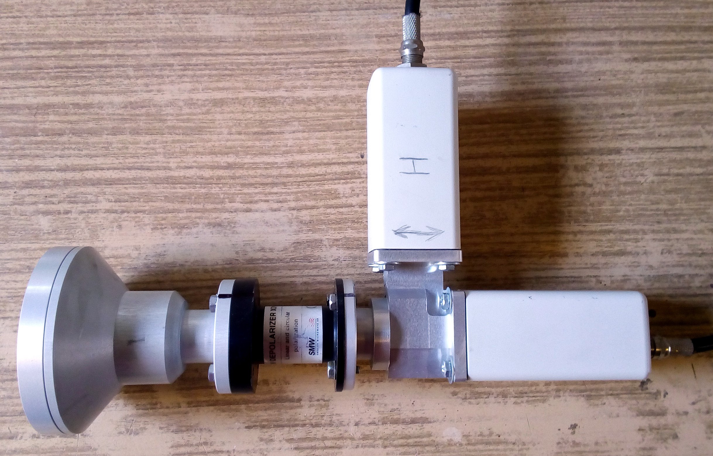
Fig. 8 - Assembly with XD12 depolarizer
The measured values with this assembly are in the third column. The signal strength is already more balanced in the entire frequency band, but decreases again at the highest frequencies. At this point, I have to admit that the measured values in the first three columns are very unstable. They fluctuate by more than 10% within one minute. So the given numbers are more of a qualified estimate. Given the mostly small differences within one line, these results are actually completely misleading. The receiver constantly adjusted the AGC and thus the strength of the resulting signal. That's why I decided to try one more time.
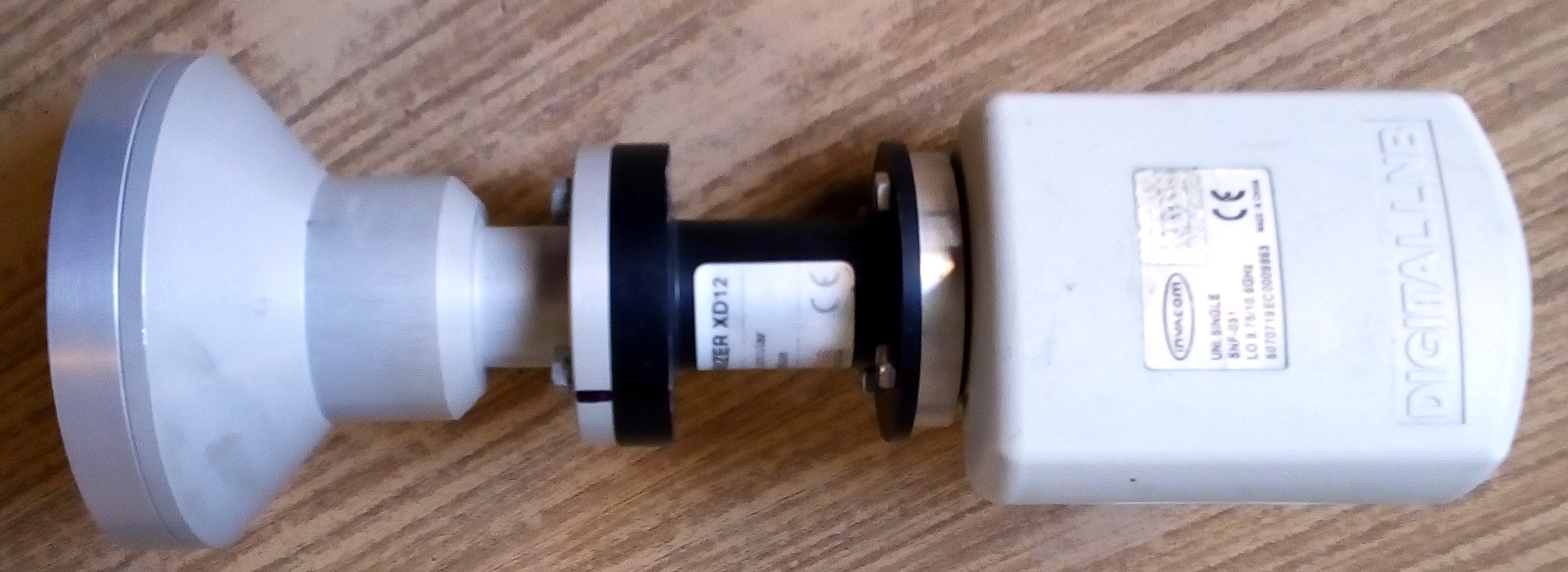
Fig. 9 - Assembly with LNB SNF-031 and depolarizer XD12
I connected an Invacom SNF-031 LNB to the PO-40 feedhorn and the XD12 depolarizer. I have had the best results with this LNB hunting for signals at 28.2°E, so I was curious to see how it would perform here. You can find the result in the fourth column of the table. At the lower frequencies, the results are comparable to the previous combination of two NJR2842 LNBs with a polarization switch, but at the upper end of the band it clearly wins. However, the most important change will probably be that the signal strength stopped pulsating and changed by a maximum of +/- 1%. The result is a little sad from the point of view that a cheap universal LNB achieves comparable results as two relatively expensive single-polarity Japanese LNBs with a polarization switch. And even better results can still be achieved with LNB GI-121 (first table, first column), where the relatively expensive XD12 depolarizer is not even needed. The sad conclusion of today is probably the realization that I still have no idea what is actually going on in that pipe between the feedhorn and the LNB. And that ignorance cannot simply be compensated with money.