
")
")
")
Chaparral Corotor II Mount
I have had the dish for some time now, so I decided to finally try the C band. The CHAPARRAL COMMUNICATIONS COROTOR II PLUS WIDEBAND FEEDHORN was already waiting impatiently on the shelf with the massive LNB Norsat 3220. The problem, however, is how to attach this system to the dish holder. The holder is designed for the KU band (40 mm socket ø) and the dimensions of the equipment for the C band (66 mm socket ø) are incomparable. It was clear from the beginning that I had to come up with some kind of reduction. And it was also clear that this would only be a temporary test solution. Using any reduction will move the C-band feedhorn out of optimal focus. In the future I will have to make a whole new dish arm, but I don't want to do that yet.
Finally, I designed a plastic reducer that screws onto the existing bracket instead of the original socket. In this reduction, there is a sufficiently large cylindrical surface to accommodate the C band device. Everything is secured with a new sleeve. The reduction must have sufficient strength and stability, as the Chaparral - LNB system weighs almost 2 kg. Figure 1 shows a drawing of said reduction.
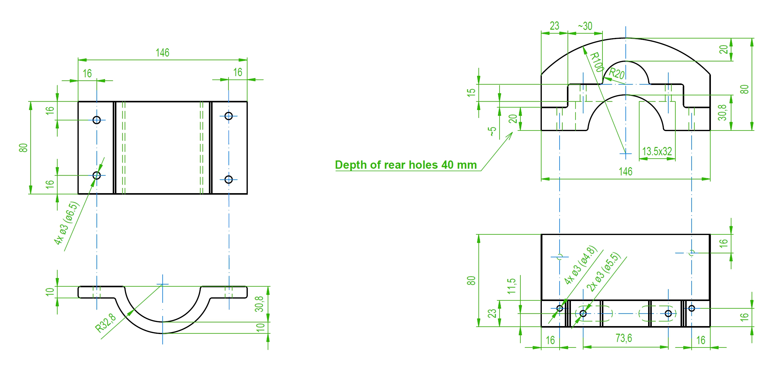
Fig. 1 - reduction drawing for C-band device
I do not claim that the above drawing is guaranteed to be correct from an engineering point of view. But it is sufficient for production. I knew from the beginning that the reduction would be printed on a 3D printer. Therefore, I asked a colleague to draw a 3D model in Solidworks based on my drawing. This procedure turned out to be advantageous also because, after viewing the model, I decided to make further minor adjustments to the design. The drawing above of course already shows the final version. Click on image 2 to see a 3D model that you can rotate and view from all sides.
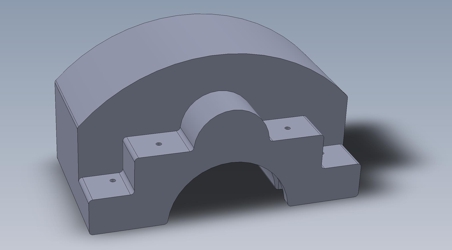
Fig. 2 - 3D model of the reduction
The reduction is attached to the support arm with M5 screws. I am anticipating placing the nuts in the reducer, so I left enough space around them for an 8-9 socket wrench. After screwing, the side wall of the reducer should rest on the support arm. The said reduction also includes a new sleeve that holds the corotor waveguide with four M6 screws. The threads for these screws are cut directly in the plastic of the reducer.
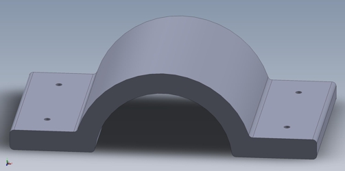
Fig. 3 - 3D model of the socket
For completeness, you can also see the sleeve in Figure 3. There is nothing interesting about its construction. Click on the image to display the 3D model again, which you can rotate and view from all sides.
The actual 3D printing is made of ASA Sapphire Blue material. Which should be an improved variant of ABS with increased UV resistance. The printing time is less than 30 hours. The total consumption of printing string is approximately 450 g. At today's prices (May 22, 2023), this amounts to approximately CZK 370. The printing position is oriented so that the cylindrical surface for the corotor waveguide is vertical and the more massive part of the body is at the bottom. In the space for the M5 nuts, it is necessary to create supports so that the upper wall does not collapse during printing. Once printed, the supports are easily removed by breaking out. I was originally thinking of having the mounting holes printed to the correct dimensions. But all holes are oriented horizontally when printed. Regardless of their size, they unfortunately had a cylindrical profile when printed. Instead of additional supports, I decided on a symbolic diameter of 3 mm, and only in the finished reduction are the holes redrilled to the correct size. The files needed for production can be found here.
The sleeve is connected to the base of the reducer with four M6 x 40 mm screws. The holes in the sleeve therefore have a diameter of approximately 6.5 mm. Opposite them are 4.8 mm holes, into which the M6 thread is cut. The front two holes are drilled through the entire thickness of the material, i.e. space for a thread of about 20 mm. The back two holes end in the reduction material about 40 mm deep. The taps I have available have a cutting length of only 15 mm. However, the plastic is so soft that the screws push out the thread to the required depth when tightening. The screws of the original bracket are M5. The holes for them will be approximately 5.5 mm. The length of the original 20mm screws is not enough and I had to replace them with 35mm screws. It is worth noting that the original screws have a narrow head Ø 8 mm for tightening with an Allen key. There's a reason for that. The space for the screw is small in the arm and a larger head and any washer will not fit there. Therefore, the nut is always from the side of the original sleeve / reduction. I used a hex head screw without a washer.
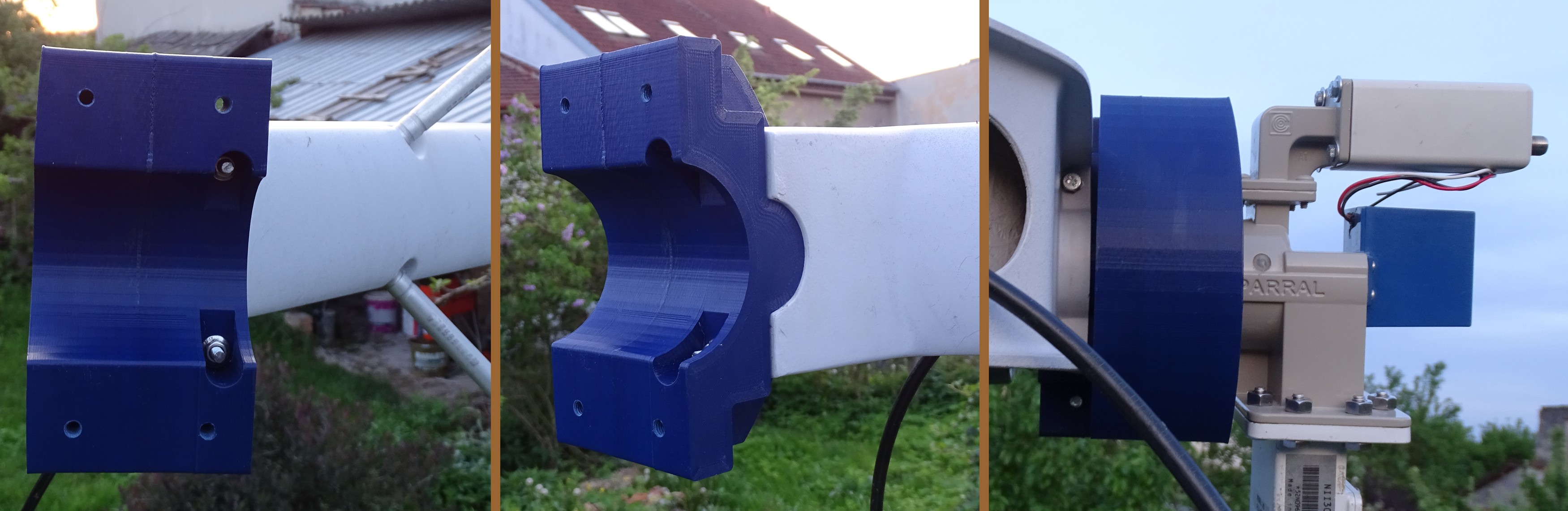
The next picture shows the completion of the reduction. Hiding the nuts and ends of the M5 screws for attachment to the arm in the body of the reducer was successful. Next you can see the location of the M5 screw head, which comes out quite tight. What didn't work is the lateral alignment of the reduction and the arm. After screwing, there was a gap of about 2 mm. It can also be seen that the upper gap is somewhat larger. This will most likely cause the feedhorn to be misdirected. To correct the fastening, it will probably be enough to enlarge the mounting holes.
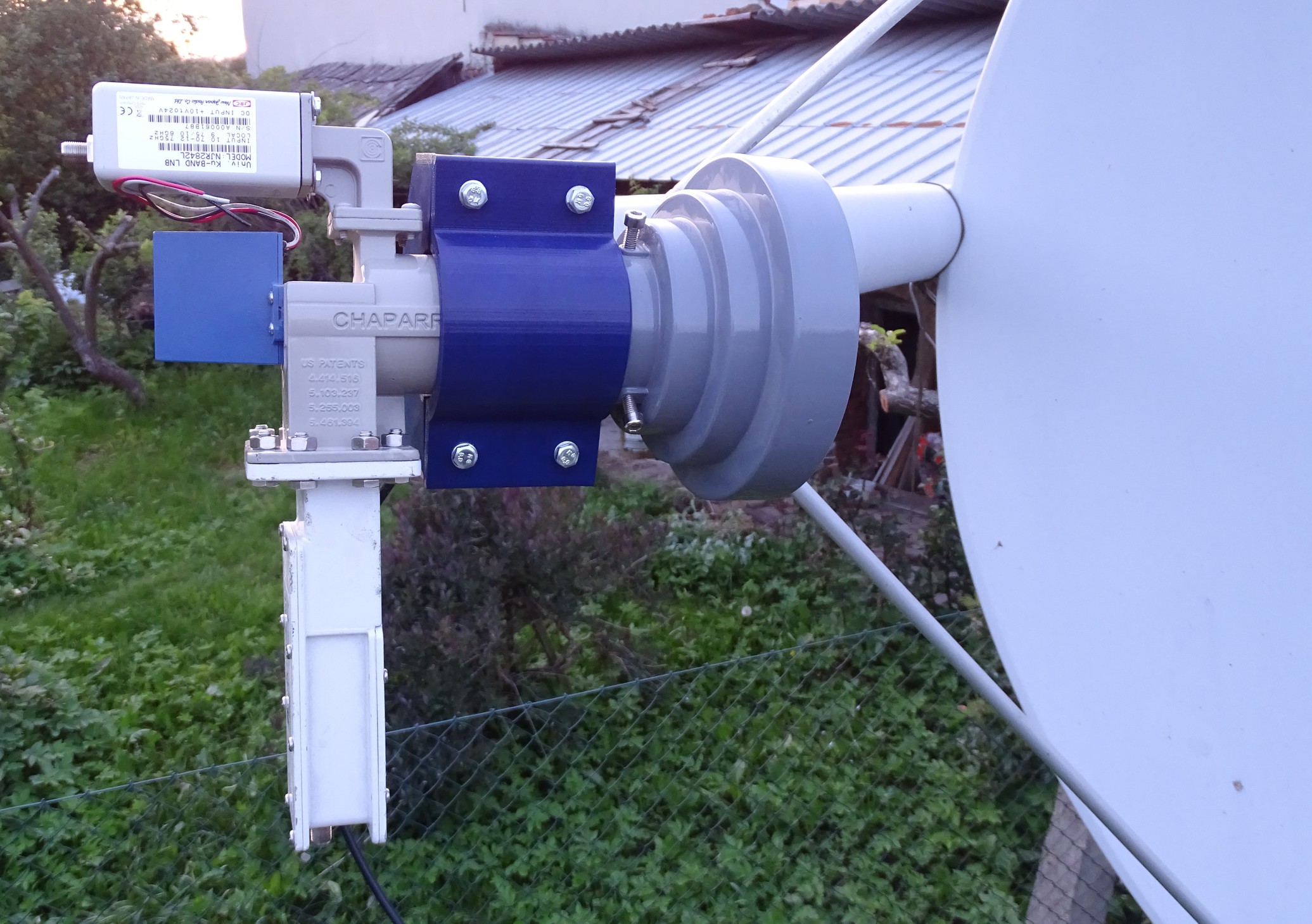
Fig. 5 - A view of the installed Chaparral
And one more overview of the installed equipment. The M6 screws are tightened tight enough that the Chaparral won't turn even with mild force. Nevertheless, there is a gap of approximately 5 mm between the screwed parts. This indicates sufficient flexibility and strength of the plastic used. Chaparral is fixed really stably and its weight is not a problem either. Now to pick up some signal.
28/5/2023 Appendix.
I didn't expect that catching the first signal would be easy. Several factors spoke against it. I had no experience with the C-band. I didn't even know how to set up the receiver. This was the first time using the Chaparral and I didn't know exactly where to attach the feedhorn to the waveguide. I didn't even verify the functionality of the LNB. But mainly thanks to my reduction, the whole device was out of optimal focus. Still, I secretly hoped that the dimensions of the dish would solve most of these problems and I would catch "at least something". Unfortunately, the miracle did not happen.
I chose 10.0°E as the first position for the tests. Here seemed to be the strongest signal available from the entire orbit. Lyngsat promised up to 41dB. But the signal was zero on all transponders. I suspected that the main problem would be the direction of the feedhorn. Therefore, I moved the parabola around the optimal direction for a while. But the signal was still at zero. I checked where on the dish the feedhorn is pointed. And even with the naked eye it was obvious that he was aiming very high. It was necessary to support the waveguide in the sleeve so that the direction was closer to the right place. The question was by how much.
I happened to find a piece of green plastic 4mm thick. So I tried it. I loosened all the sleeve screws, added this piece to the edge and retightened the screws. It could be seen that the feedhorn routing had shifted to the second half of the parabola.
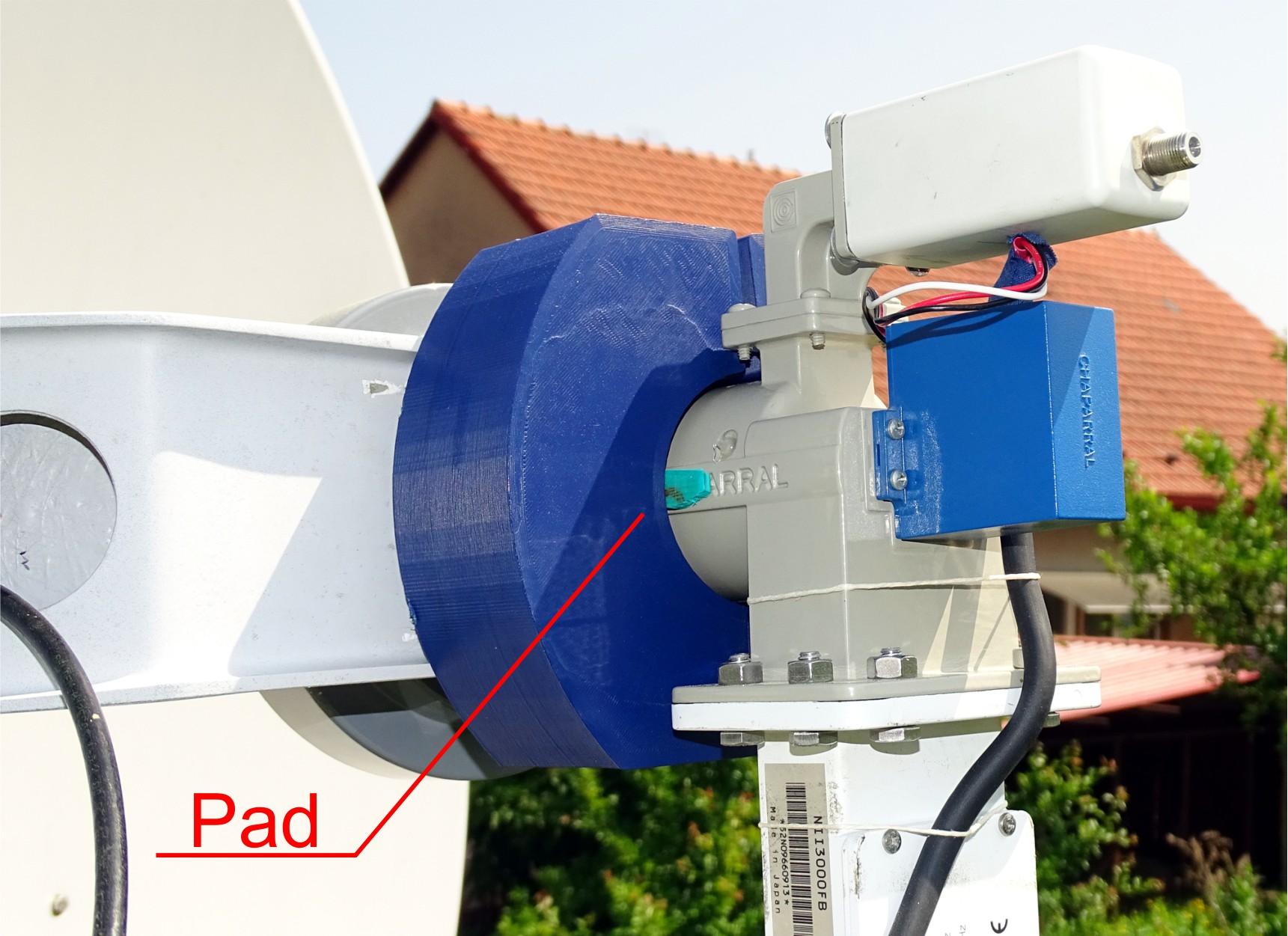
Fig. 6 - Chaparral Rerouting Pad
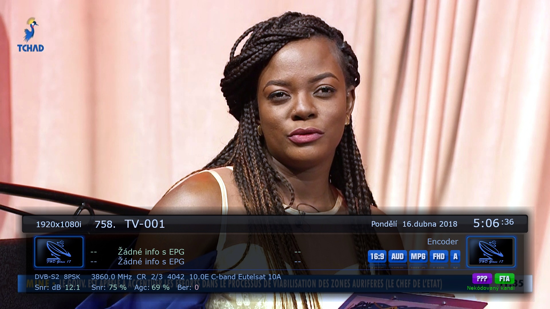
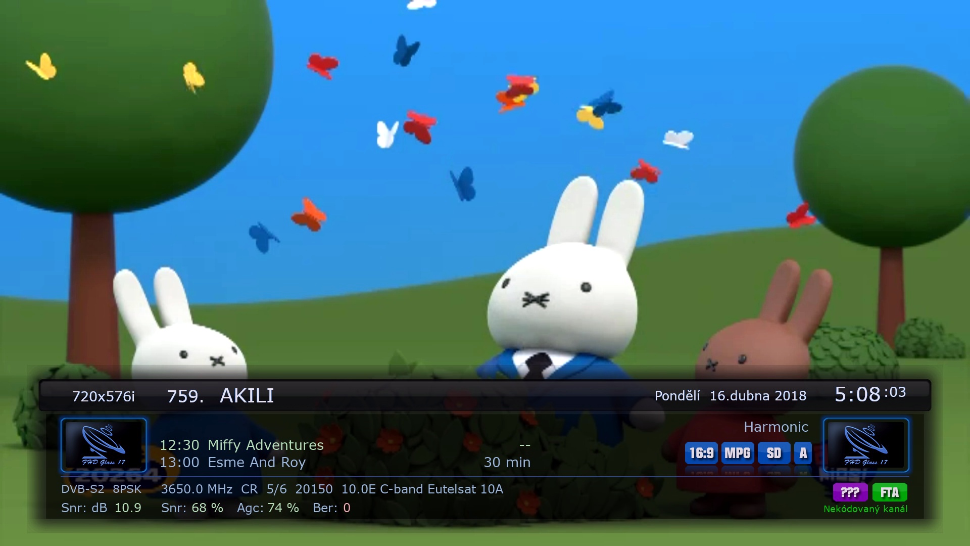
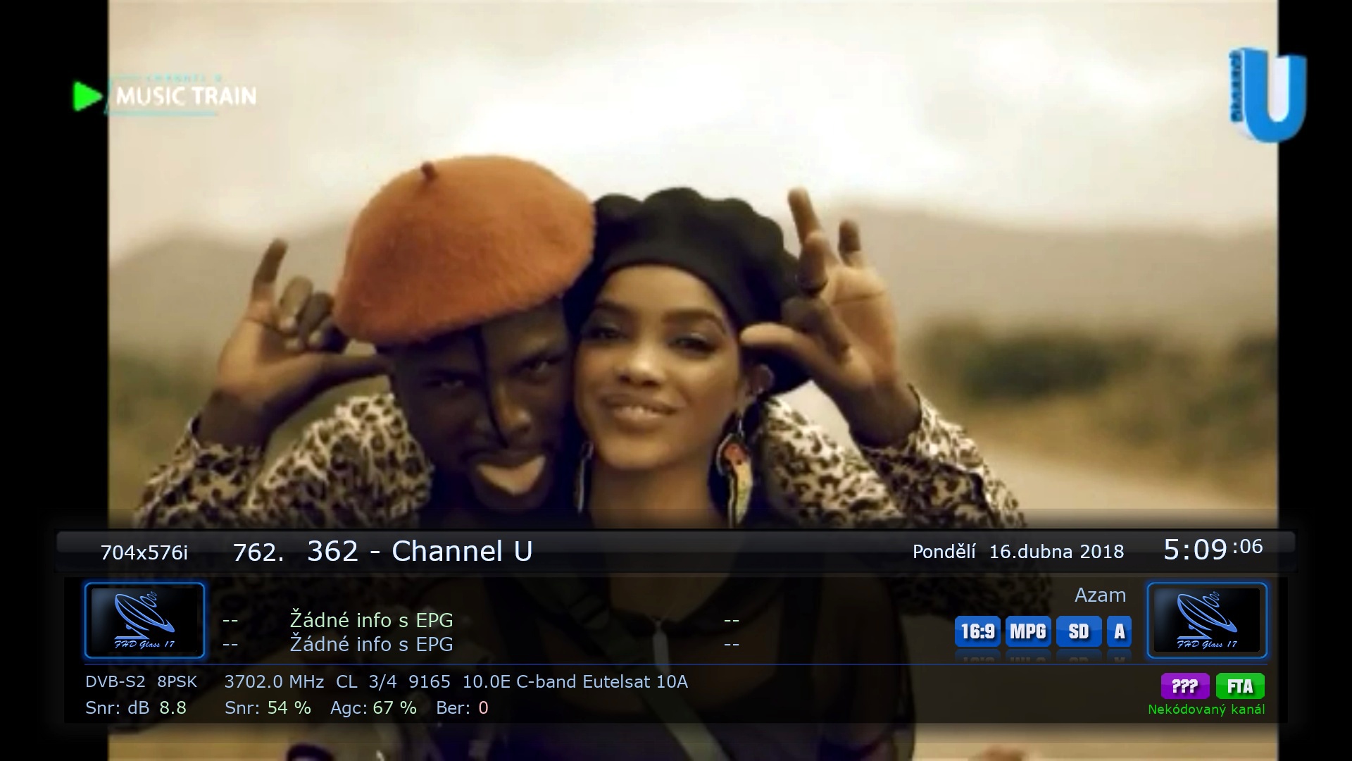
I tried the signal again and again it was zero. But changing the direction of the feedhorn could affect the direction of the whole dish. So I shot the parabola a little more to the east. And glory, the signal went up !!! So I tuned the whole band. Since my positioner can't rotate the Chaparral servo depending on the polarity of the transponder, I had to tune twice. First right-handed polarization and then left-handed. I have the strongest signal at the frequency of 3860 MHz - 12.1 dB, the weakest at 3702 MHz - 8.8 dB. I tuned around our noon, but I don't know yet if the time of day has an effect on the signal strength. Now I'm going to enjoy the success with the new toy for a while. Then I'll try to move everything that can be adjusted and see if I can get a stronger signal.
At the end, I'm adding a few pictures of today's captured broadcast. The strongest signal in HD resolution, the program in SD resolution with a higher data rate and the weakest signal in the opposite polarity.
20/6/2023 Appendix.
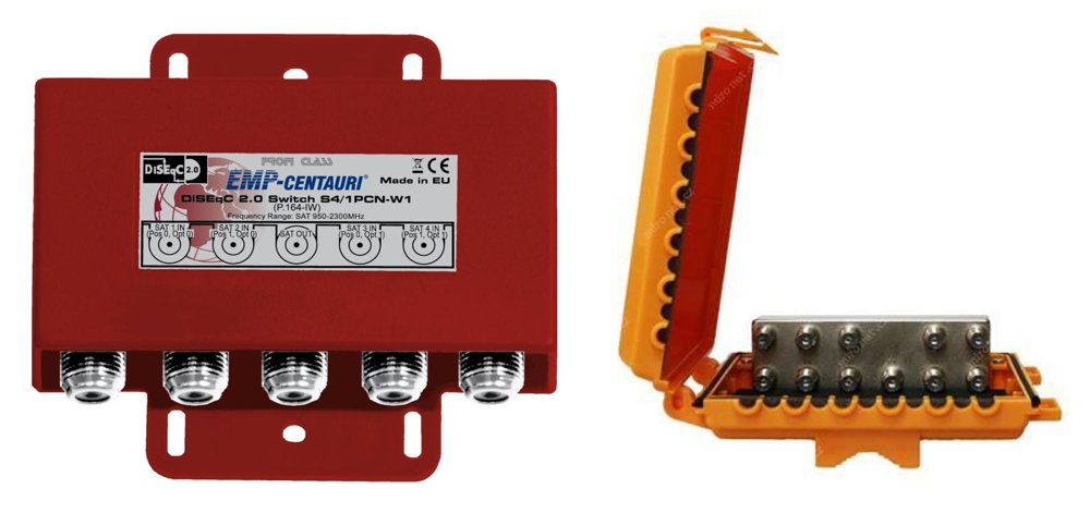
For my first C-band experiments I used a 4-input DiseqC EMP-Centauri switch. At times I had the impression that the signal jumped reluctantly after switching to C-band. But I didn't pay too much attention to it. I was new to this band and transponders with low data rates take a bit of time to start up. But then I replaced this switch with a 10-input Amiko and lo and behold, the signal from the C-band was permanently zero.
First I looked for a bug in the new satellite receiver setup. For the original switch, I used DiseqC 1.0 commands, while for the new switch it was necessary to switch to DiseqC 1.1 commands. However, any attempts to change the settings had no effect. I tried to use the old AZBox instead of the VU+Ultimo4k receiver. This changed both the HW and SW sending DiseqC 1.1 commands. But the result was still the same. So I turned to my more experienced colleagues. And they advised me to try powering the Norsat 3220 LNB from an external source. Allegedly, when the receiver resource is overloaded, the DiseqC commands are "garbled" and the switch does not understand them. That didn't seem very likely, but I had to check. First I measured the consumption of the LNB Norsat 3220. I got about 290 mA. Then I tried how much the supply voltage on the coaxial cable from the receiver drops after connecting this LNB. The result was already beginning to indicate something. After connecting the LNB, the supply voltage dropped from 13.72V to 12.57V and with the opposite polarity from 18.72V to 17.57V. So I bought a power crossover.
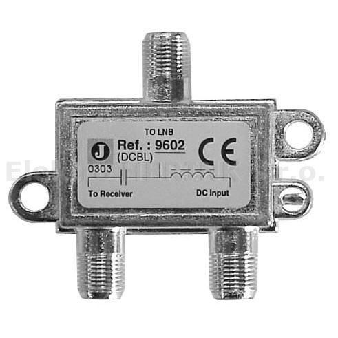
Fig. 8 - Johansson 9602 Satellite Crossover
First of all, I must say that buying a crossovers for satellite reception, i.e. for the 950 to 2300 MHz band, is not easy. Uncle Google constantly forced me to use crossovers for terrestrial TV broadcasting, i.e. the frequency range of 5 to 900 MHz. In the end, however, I managed to get a Johansson 9602 crossover with a through current of up to 0.5 A. Which suits my Norsat. I used the already mentioned AZBox receiver as a power source and an old, discarded white coaxial cable for the connection. And to my surprise, everything works as it should. The Amiko switch also switches to C-band.
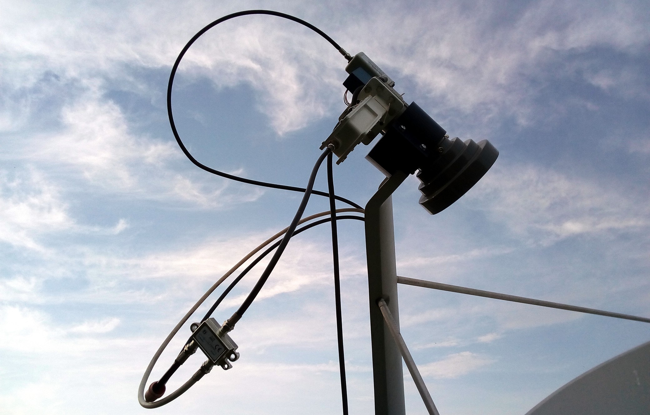
Fig. 9 - Connected Crossover to LNB Norsat 3220
I'm glad the switching issue was resolved. But it raises more questions for me. It would never have occurred to me that the fault lies in excessive loading of the receiver source. After all, positioning motors powered by a coaxial cable from the receiver are commonly produced. I have never used such a motor, but I do not believe that such a motor with a consumption much lower than my 300 mA can handle rotation with a parabola with a diameter of perhaps 90 cm. Such a motor cannot be controlled via the DiseqC switch? So if I have 4 fixed dishes (so that I don't have to wait for the motor to readjust for selected satellites) and a fifth dish on the motor, how do I connect it all to one input of the receiver?
Corotor is designer for prime focus dish f/d ,not for offset.