
")
")
")
Diagram and description of the proposed HW 1.0
I tried the above scheme and it works. I made a prototype on which I test the first software attempts. It may not belong here yet, but I would like to warn all those interested in building a small catch. This HW assumes that the input GPIO pins to the Raspberry Pi will have activated internal pullup resistors at + 3.3V. By default, these resistors are disconnected. However, some software libraries cannot activate pullup resistors. In that case, it must be turned on when Raspberry Pi is started by adding an entry to the text file config.txt. I will remind you in the section dedicated to software.
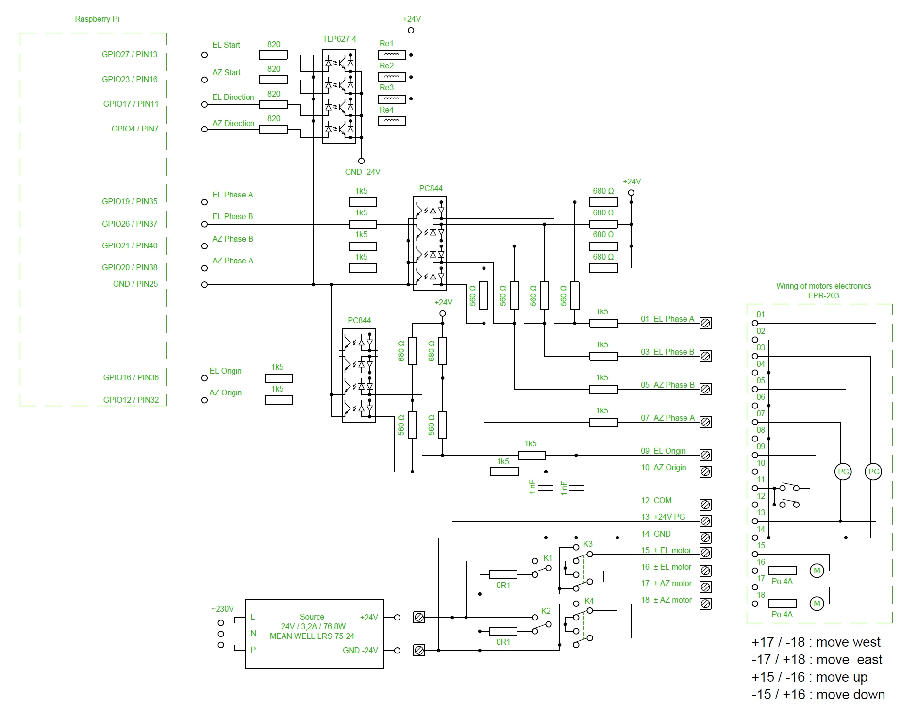
Fig.1 - Diagram of the proposed modification
The connection to the Raspberry Pi will be via a GPIO port. The issue of compatibility must first be addressed. Older Raspberry Pi computers were manufactured with a 26-pin GPIO connector. The newer Raspberry Pi 3 and 4 have a 40-pin GPIO connector. Older Raspberry Pis would probably be good enough, but there are few free pins. Some pins have more functions, so it is difficult to judge which ones to use.
In the end, I decided that I would not support the older Raspberry Pi with a 26-pin connector, because choosing the new Raspberry Pi pins, which are also available on older versions, would be an unnecessary complication. In addition, I am thinking about controlling another HW, for which there are not enough free pins on the old versions. Therefore, backward compatibility would still not be possible in the future. This practically means that if someone uses an older Raspberry Pi with a 26-pin connector, they will have to adjust the software accordingly and, in addition to controlling the positioner, will no longer have HW reserve for anything else. The description of the GPIO connector is shown in the following figure.
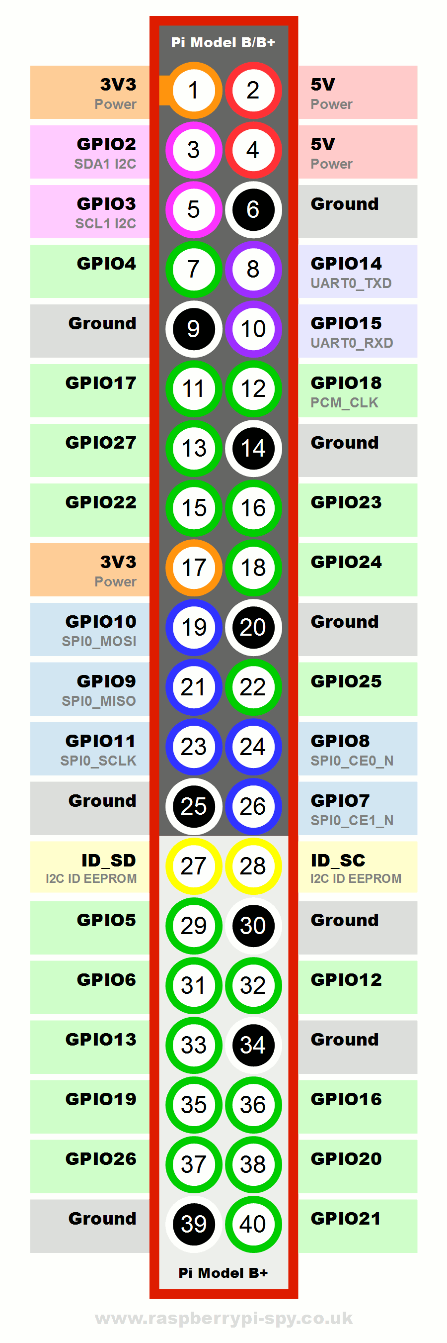
Fig. 2 - Description of the Raspberry Pi GPIO connector
We will need four outputs from the computer:
- GPIO27 (Pin13) Switch elevation motor on / off
- GPIO23 (Pin16) Switch the azimuth motor on / off
- GPIO17 (Pin11) Change the direction of the elevation motor
- GPIO4 (Pin7) Change the direction of the azimuth motor.
We will need six inputs to the computer:
- GPIO19 (Pin35) Elevation motor sensor A
- GPIO26 (Pin37) Elevation motor sensor B
- GPIO20 (Pin38) Azimuth motor sensor A
- GPIO21 (Pin40) Azimuth motor sensor B
- GPIO16 (Pin36) Elevation zero switch
- GPIO12 (Pin32) Azimuth zero switch
Switching a relay is the simplest part. The output of the TLP627-4 optocoupler can withstand voltages up to 300V and currents up to 150mA, so it can switch the relay coil directly. It also contains a fast antiparallel diode for inductive loads. The current of the input LED diode of 2 mA is enough for reliable switching, which reliably withstands the raspberry Pi output GPIO pins at a voltage of 3.3V.
With input signals it is a bit more complicated. I took inspiration from the diagram of the original device. The 1k5, 560 and 680 ohm resistor network ensures sufficient current through the input LEDs of the PC844 optocoupler. The LED lights up when the sensor output is 0V, which limits its power load. At that moment, the output phototransistor closes, which connects the input GPIO pin to ground via a protective resistor 1k5. The zero switches operate in the same mode. They are supplemented by 1nf filter capacitors filtering induced high-frequency interference. After all, just 2m of wire is already a sufficient antenna that will catch where what.
The following table lists the components used:
| Part number | Component name | Quantity |
|---|---|---|
| 1 | Resistor 0R1 5W 5% | 2 |
| 2 | Resistor 560Ω | 6 |
| 3 | Resistor 680Ω | 6 |
| 4 | Resistor 820Ω | 4 |
| 5 | Resistor 1k5 | 12 |
| 6 | Condenser 1nF | 2 |
| 7 | Optocoupler TLP627-4 | 1 |
| 8 | Optocoupler PC844 | 2 |
| 9 | Relay OMRON G2R-1-DC24 | 2 |
| 10 | Relay OMRON G2R-2-DC24 | 2 |
| 11 | Terminal blocks ARK500/2EX | 8 |
| 12 | Connector MLW40G | 1 |
| 13 | Source MEAN WELL LRS-75-24 | 1 |
| 14 | Raspberry Pi3 + Source + SD card | 1 |