
")
")
")
Scheme and description of the proposed HW 2.0
So far, this scheme is just my idea. I am in the process of preparing an experimental prototype. If anyone would like to comment on the scheme with advice and comments, I would be happy. Whether in the comments at the end of the article, or in the discussion forum here. As soon as I check the functionality of the design, I will write more info here.
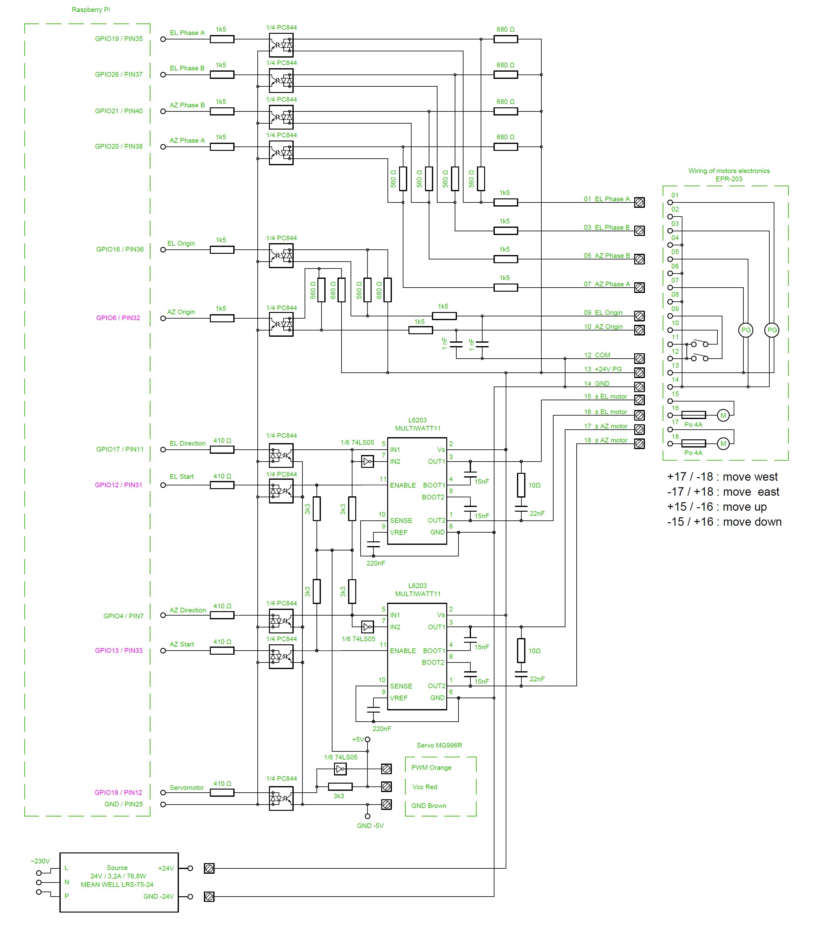
Fig.1 - Schematic of the proposed HW 2.0 connection
The connection with the Raspberry Pi 3 GPIO pins will be different than with HW version 1.0. The reason is the PWM HW channels and the servomotor control, which have fixed pins, but in HW 1.0 these pins were already used for something else. The description of the GPIO connector is shown in the following figure.
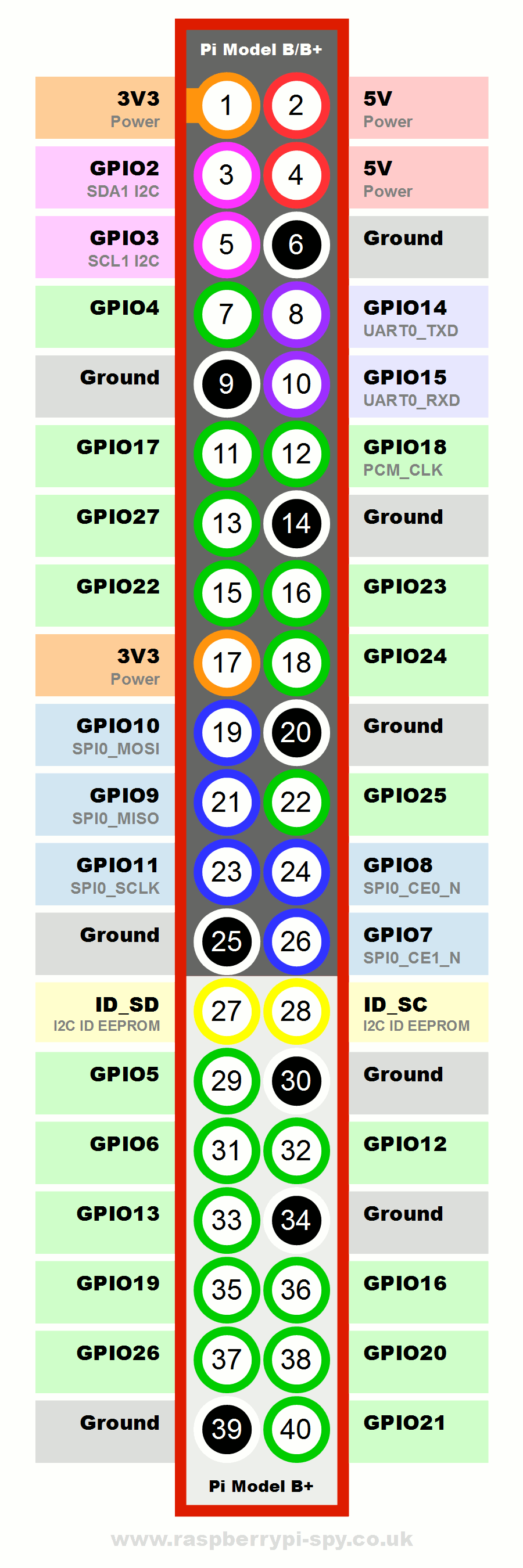
Fig. 2 Description of the Raspberry Pi GPIO connector
The outputs from the computer are redistributed as follows:
- GPIO12 (Pin32) Switch elevation motor on / off (HW PWM)
- GPIO13 (Pin33) Switch the azimuth motor on / off (HW PWM)
- GPIO17 (Pin11) Change the direction of the elevation motor
- GPIO4 (Pin7) Change the direction of the azimuth motor
- GPIO18 (Pin12) Servomotor control (HW PWM)
The inputs to the computer are newly arranged as follows:
- GPIO19 (Pin35) Elevation motor sensor A
- GPIO26 (Pin37) Elevation motor sensor B
- GPIO20 (Pin38) Azimuth motor sensor A
- GPIO21 (Pin40) Azimuth motor sensor B
- GPIO16 (Pin36) Elevation zero switch
- GPIO6 (Pin31) Azimuth zero switch
The mentioned use of pins is still temporary, it can still change during the design of the printed circuit board thanks to optimization.
The outputs from the Raspberry Pi 3 first go to the isolating optocoupler, which should protect the GPIO pins with a voltage of 3.3V. In this construction, however, the situation is somewhat more complicated than in HW version 1.0. The L6203 power excitation bridge is controlled by a voltage of 5V. A separate power supply should be used for this voltage. But that seems too exaggerated to me so far. I want to test if it will be enough if 5V for my board does not go through the circuits of Raspberry Pi 3. The supply voltage from the 5V source goes first to my printed circuit board and only then is it fed to the computer. I know it's wrong. In case of failure of L6203, the 24V voltage can get this way to the Raspberry Pi 3. But for now I want to try it like that.
The inputs IN1 and IN2 of the L6203 circuit decide what voltage will be at which output. For my use, it must always be in the opposite phase. This is provided by the 74SL05 circuit, or one of its gates. This switches the polarity of the voltage on the controlled motor. The rotation speed is controlled by the ENABLE input. The principle of PWM is that the supply voltage is supplied to the motor in the form of pulses. The frequency of these pulses must be adapted to the design of the motor, but is usually 50 to 200 Hz. The alternation of these pulses then determines the speed of rotation of the motor. The advantage of this method of speed control is that the full supply voltage is always connected to the motor, so that the motor power at low speed is not reduced too much. What frequency I will use in my design I will have to find out experimentally according to the behavior of the motors. A 0% shift means that the engine is off. 100% shift means the engine runs at full speed.
The MG996R servomotor can be controlled directly by a 5V signal according to the TTL standard. Therefore, no power switching element is required. To be sure, I used an isolating optocoupler here as well, but it reverses the polarity of the signal. Therefore, we must return it to its original state by a gate from the 74LS05 circuit. Although the servo is designed for a supply voltage of 6V, even 5V is sufficient for sufficient motor power. The control principle of the servomotor is the same as for PWM. The difference is that the range of control pulses is precisely defined and relatively narrow. A frequency of 50 Hz is used, ie the length of one period is 20 mS. A pulse length of 1.5 mS sets the servo rotor to the middle position. A pulse length of 0.5 mS sets the rotor to one extreme position and a pulse length of 2.5 mS to the other extreme position.
Input signal processing is designed in the same way as in version 1.0. The input resistor network supplies the LEDs in the isolating optocouplers. So far, I am considering two variants of HW, 24V for EGIS and 36V for traction motors. If the same resistance network can be used for both supply voltages, I will check experimentally on the first prototype. I will measure the currents through the input LEDs of the optocouplers and according to the found values I will decide for the final variant. Although I do not change anything fundamental in the construction of the inputs, I would like to test whether everything will work reliably even when connected to EGIS with unshielded cables with a length of 10 m. This length of cables would, in my case, make it possible to hide the control electronics in the attic of a nearby house. This would simplify weather protection.
The following table lists the components used:
| Part number | Component name | Quantity |
|---|---|---|
| 19 | 40 pin flat IDE cable | 1 |
| 18 | Raspberry Pi 3 + Source + SD card | 1 |
| 17 | Source MEAN WELL LRS-75-24 | 1 |
| 16 | Connector MLW40G | 1 |
| 15 | Terminal blocks ARK500/2EX | 2 |
| 14 | Terminal blocks ARK500/3EX | 4 |
| 13 | Condenser 220nF | 2 |
| 12 | Condenser 22nF | 2 |
| 11 | Condenser 15nF | 4 |
| 10 | Condenser 1nF | 2 |
| 9 | Resistor 3k3 | 5 |
| 8 | Resistor 1k5 | 12 |
| 7 | Resistor 680Ω | 6 |
| 6 | Resistor 560Ω | 6 |
| 5 | Resistor 410Ω | 5 |
| 4 | Resistor 10Ω | 2 |
| 3 | Hex Inverter With Open-Collector Outputs SN74LS05 | 1 |
| 2 | Optocoupler PC844 | 3 |
| 1 | DMOS FULL BRIDGE DRIVER L6203 | 2 |