
")
")
")
HW version 2.1 solution design
Over time, what I suspected at the beginning became apparent. My new control unit will not only be a replacement for the original EPS-103. Satellite reception requires a lot more equipment to control than just two motors to adjust azimuth and elevation. First, I planned to add a single servo control to adjust the SKEW. But then the project started to grow a bit.
The basis is still the Raspberry Pi computer. I use model 3 B. Older RasPis do not have sufficient HW equipment. I haven't considered the RasPi4 yet. But its use will certainly be possible.
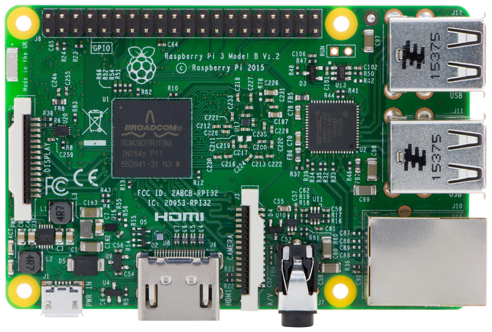
Even the resource still remains the same as in HW version 1.0 or 2.0. It has sufficient performance and important damage protection. I have been using it for the second year and it has proven itself.
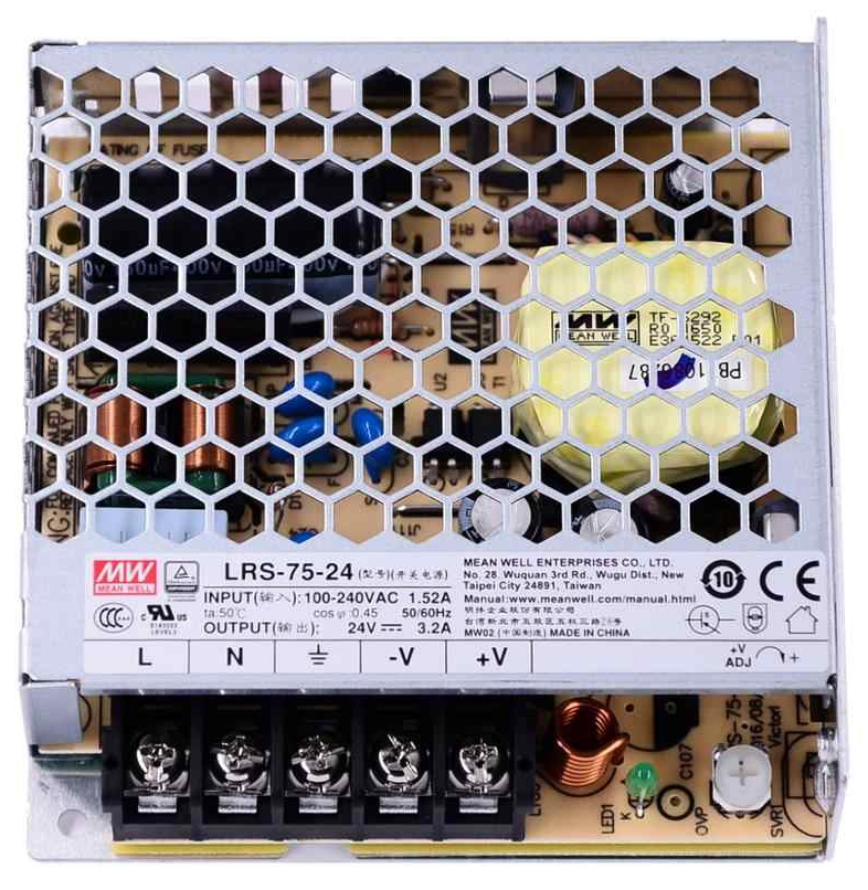
Fig. 2 - Switching power supply module MEAN WELL LRS-75-24
The first new feature compared to HW version 2.0 is the control of a small geared DC motor. I found it in this shop www.dcmotory.cz and it has interesting properties.
| Designation: | PG320-24-264-BE |
| Power voltage: | 24V DC |
| Gear: | 1:264 |
| Bearings: | Ball, metal |
| Rotation sensor: | Hall sensors 2x |
The motor seems to be ideal for creating a whole LNB shooting system - SKEW setting. Its control can be completely identical to the control of EGIS main engines. That is, speed control by PWM modulation using the L6203 circuit. It's unnecessarily strong, but at least it won't get too hot. Motion feedback is provided by two Hall probes.
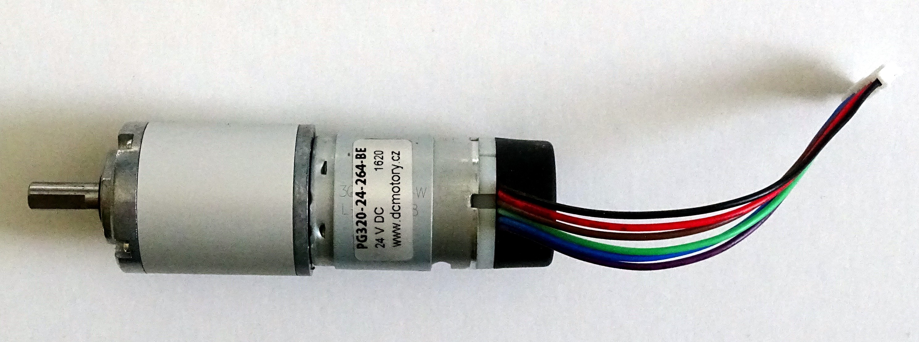
Fig. 3 - Engine PG320-24-264-BE
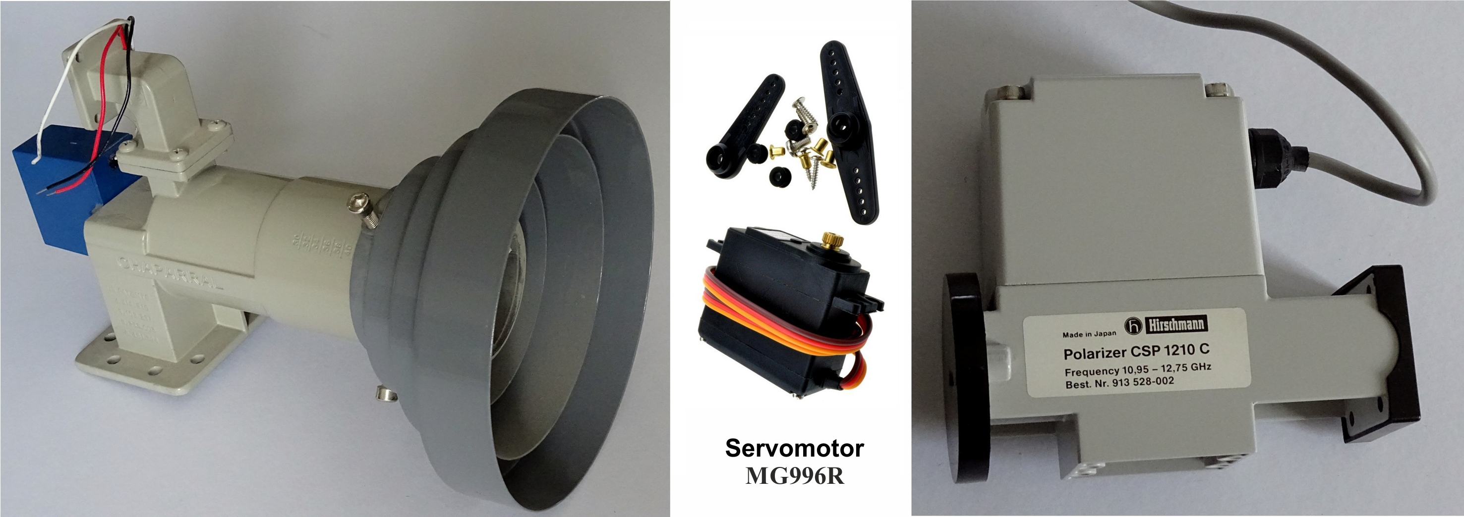
Another novelty is the control of the second servo motor. Since the use of servo motors is quite widespread in satellite technology, two servo motor interfaces may be useful. In the original HW.2.0 build, I considered using the MG996R modeler engine to adjust the skew. But for example the Corotor Chaparral or the Polarizer Hirschmann CSP 1210 C also use a servo motor.
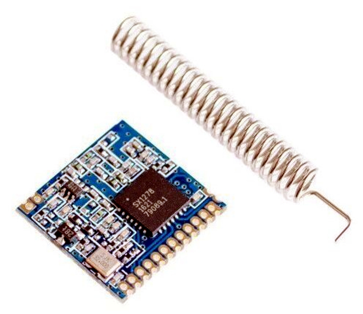
It turns out that this project could be expanded further in the future. To prepare for this, I decided to route some buses from the RasPi's 40-pin connector to separate terminals. Additional peripherals can be easily connected if desired. For example, weather station sensors. Owners of large dishes are certainly interested in how strong the wind is in the immediate vicinity of their dish and in which direction. There are certainly more such accessories. And the transfer of this data to the RasPi could be, for example, a 433MHz module connected to the SPI bus. The use of the I2C bus is also sure to be found.
But that's really far in the future. So let's finally get down to business.