
")
")
")
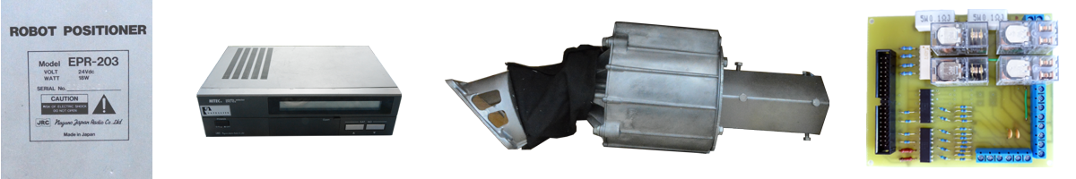
HW 1.0 solution design
I have set the following basic requirements for the new control unit:
- Control both azimuth and elevation motors simultaneously
- Possibility of expansion to control other elements, such as the motor for setting the skew LNB
- Place the control unit in close proximity to the rotator, control everything via Ethernet, either by cable or via Wi-Fi
- Do not interfere with the electronics of the motors. In case of failure, the original device can be used.
From these initial considerations, it was clear that the choice would be my favorite Raspberry Pi 3. The universal computer allows the creation of any software and therefore any future extensions. The GPIO connector, in turn, offers a simple interface for controlling the rotator hardware. The computer is small and can be placed in a waterproof box on the rotator mast. Only the 240V supply voltage will need to be introduced into this box, so no additional cable is required for Wi-Fi communication. If we prefer to choose cable communication, we have an Ethernet connection available up to 85m according to the standard. And we do not have to dramatically solve the interference of cables connecting the rotator and the computer located in its immediate vicinity (up to 2m).
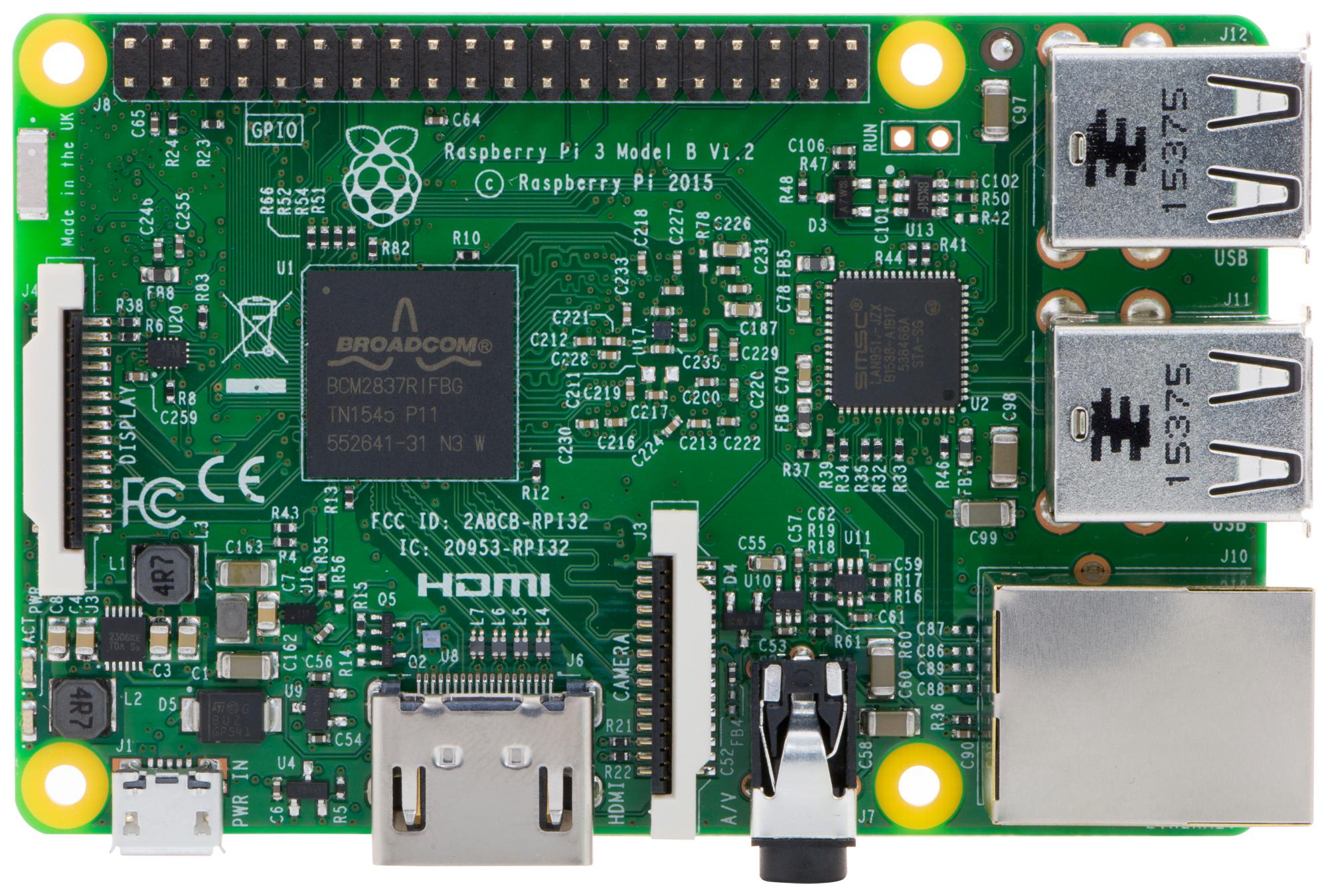
Fig. 1 - Computer Raspberry Pi
I'm a little worried if such a universal computer can be used to control hardware in real time. Unfortunately, a specialized real-time operating system (such as FreeRTOS) would suppress the main advantage of the Raspber Pi, its versatility. But the performance of the computer is relatively high, so it can be assumed that the regular Linux OS Raspbian will suffice for a sufficiently fast response of the control program.
The second construction block will be a 24V power supply. Nowadays, it is already possible to buy a module of a sufficiently small, but at the same time powerful switching power supply. I finally chose the MEAN WELL LRS-75-24 type. >Its dimensions are 99x97x30mm. It is capable of delivering up to 75W, which is almost double the need for both motors to run simultaneously. And it has internal protections for overload, mains overvoltage and overheating.
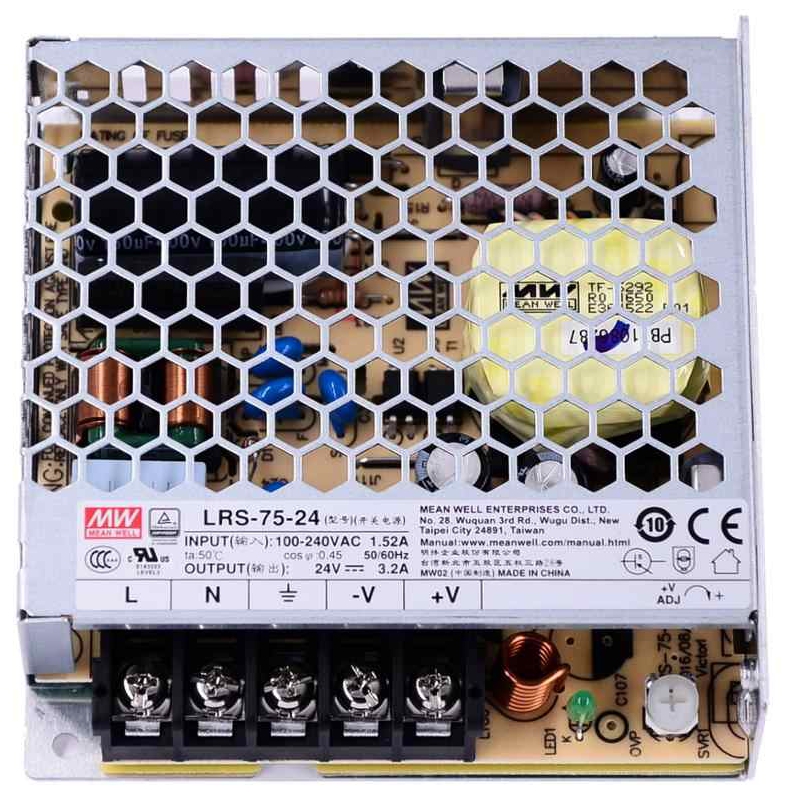
Fig. 2 - Switching power supply module MEAN WELL LRS-75-24
It is also necessary to decide how the 24V power voltage will be connected to the motors. Electronic contactless components are now available, but in the end I chose classic relays. The reason is the galvanic separation of the 24V part from the Raspberry Pi computer and the fact that they do not need cooling regardless of the switched power. This could be an advantage in the summer. Finally, I chose the OMRON G2R-1-DC24 type to turn on / off the motors and the OMRON G2R-2-DC24 to change the direction of rotation. The contacts are capable of switching currents up to 5A and the control voltage for the 24V coil can be taken from the source for motors.
It remains to figure out how the input / output signals will be converted between the 24V logic of the motors and the 3.3V logic of the Raspberry Pi. In order to consistently galvanically separate the computer from the surrounding HW, optocouplers will be used. I chose TLP627-4 for switching the relay winding and for inputs to the Raspberry Pi it will be COSMO PC844. This determines the rough outlines of the prototype.