
")
")
")
General overview - description of the original control unit EPS-103
The original EPS-103 unit is a separate device that is only intended to control the EPR-203 motor unit. It has no remote control or connection to a satellite receiver. We have to remember that the production took place sometime in the eighties of the last century. Its capabilities and used components correspond to this. Personally, I haven't considered using it at all these days. That's why my Raspberry Pi project was born. But numerous inquiries about this unit show that many people still use it. That's why I decided to devote more time to her than I originally intended.
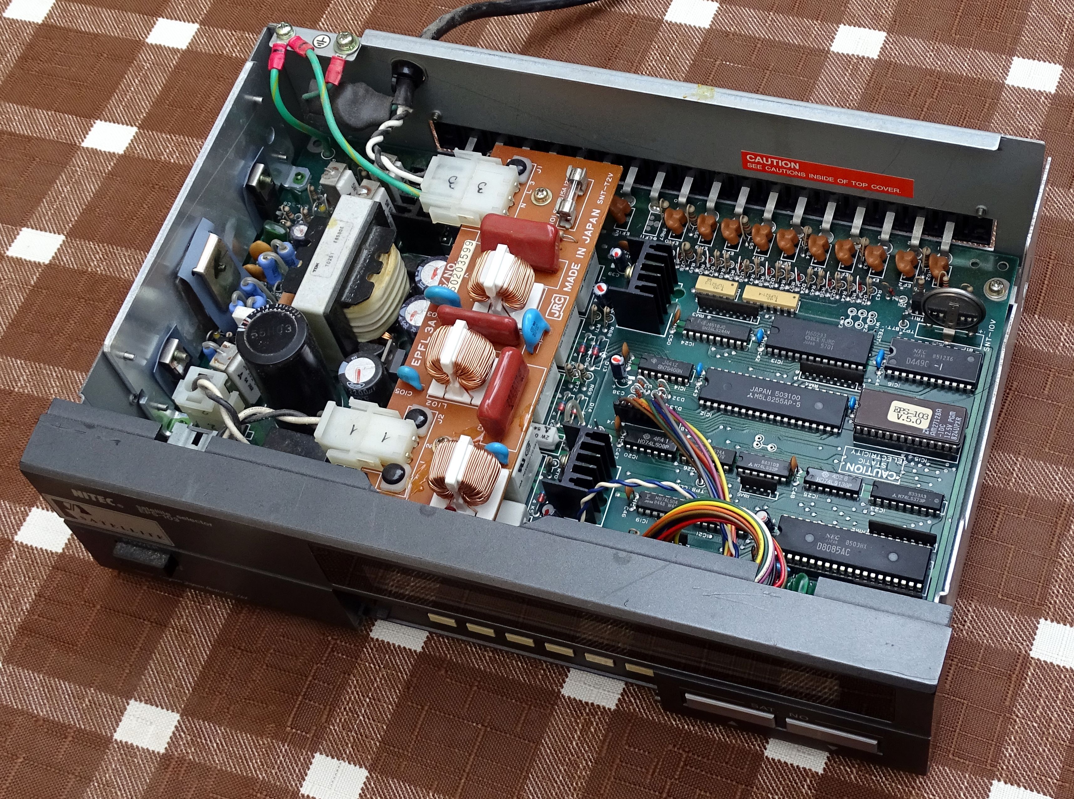
Fig. 1 - Original EPS-103 unit
You can download the manual and diagram here. The unit is controlled via a keyboard with 11 + 2 buttons and one switch. Unit status is shown on a 40-character single-line display.
The heart of the device is the D8085 processor from NEC. The program (firmware) is located in the parallel memory EPROM AM27128A with a size of 16kB. The memory can only be erased by UV radiation. Memory is approximately 2/3 full. All system and user programmable data is stored in a 2kB NEC D449C SDRAM. The memory is powered by the built-in battery when the device is off. Both memory types and all peripherals are mapped to a common address space of 64 KB. The display is a separate peripheral connected directly to the system bus. So does the OKI M60233 circuit processing impulses from the EPR-203 sensors. The remaining peripherals are connected via the 8255 circuit. These are the keyboard module and the relay module switching the voltage to the motors. An overview is in the following table.
| Address from | Address to | Component | IC | Comment |
| $0000 | $3FFF | EPROM | AM27128A | 16 kB |
| $4000 | $47FF | SDRAM | D449C | 2 kB |
| $4800 | $4803 | LCD | DMC 40131 | |
| $5000 | $5003 | M60233 | input from sensors | |
| $5800 | $5803 | klávesnice | 8255 PA, PB | dynamically scanned |
| relé | 8255 PC | engine control |
I derived the address range from the device diagram. The LCD display only communicates on four addresses: (Corrected 16.10.2022)
- Addr. $4800 = Read Busy Flag / Address Counter
- Addr. $4801 = Read Data - not used
- Addr. $4802 = Write Command
- Addr. $4803 = Write Data
The 8255A peripheral circuit is located at the following addresses:
- Addr. $5800 = R/W PA
- Addr. $5801 = R/W PB
- Addr. $5802 = R/W PC
- Addr. $5803 = Write Control Word
Control Word has the following features: (Bit 0, 1, 2 = Group A; Bit 3, 4, 5, 6 = Group B)
- Bit 0: Port C (lower): 0 = output; 1 = input
- Bit 1: Port B: 0 = output; 1 = input
- Bit 2: Mode Group A: 0 = basic I/O; 1 = strobed I/O
- Bit 3: Port C (upper): 0 = output; 1 = input
- Bit 4: Port A: 0 = output; 1 = input
- Bit 5, 6: Mode Group B: 00 = basic I/O; 01 = strobed I/O; 1x = Bi-Directional
- Bit 7: Mode Set Flag: 1 = Active
If we decide to modify the EPS-103 unit in any way, we will always have to reprogram the memory with the firmware. The important thing to note here is that this is an old type of parallel memory that has the entire address bus routed to circuit pins. This type of memory is not used much today. Therefore, it is difficult to find a programmer who can work with them. Many programmers that have a large socket for circuits up to PDIP40 only work in serial mode and are not usable for our purposes. I managed to find the USB programmer Willem Programmer GQ-4x V4, which can work with parallel memories.
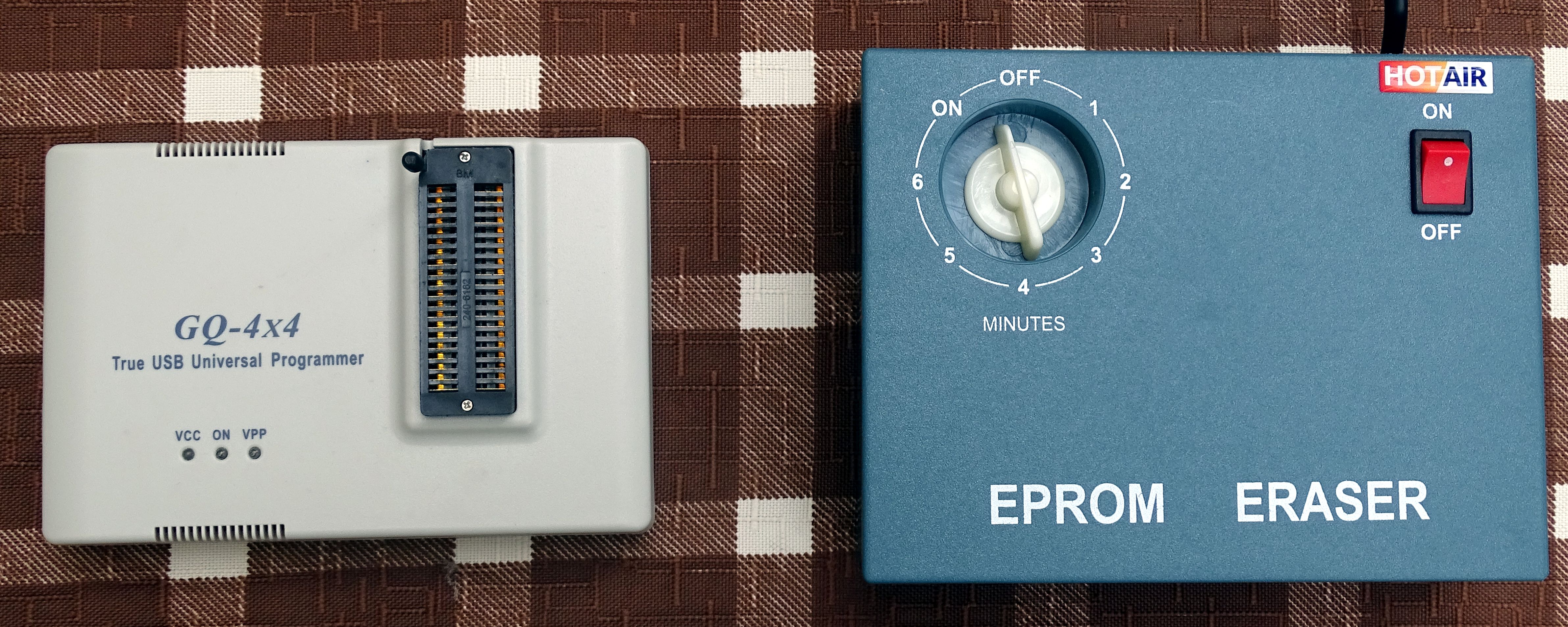
Fig. 2 – Programmer and eraser
The memory can only be erased by UV radiation. Therefore, in addition to the programmer, we will also need a UV memory eraser. Naturally, I thought of replacing the original type with a newer EEPROM or Flash memory that can be erased directly in the programmer. Unfortunately, I have not been able to find any suitable type these days. Memories with a capacity of 16kB in such a design simply do not exist anymore. You can buy memories with a larger capacity, but they have some terminals connected differently. I didn't feel like experimenting with them. Also, pay attention to the type of EPROM memory, which can be programmed, but only once. They cannot be deleted.
Since the memory in the device is located in a socket, it is relatively easy to remove and read. This gives us a basic *.bin file that we will work with further. You can download my firmware version 5.0 in the downloads / original documentation section. For comparison, you can also download the newer firmware version 5.015, which I obtained from an Egis owner. If you have firmware of other versions, send them to